

Yokogawa SNB10D-225/CU2N startup failures are commonly traced to ESB Bus configuration inconsistencies, redundant communication path errors, or power distribution problems rather than defects inside the Safety Node Unit. A structured Installation Guide helps engineers avoid commissioning delays by validating communication infrastructure before Safety Instrumented System (SIS) logic testing begins.
Contents
- SNB10D-225/CU2N Safety Node Unit Overview
- SNB10D-225/CU2N Safety System Applications
- Project Planning Before Installation
- ESB Bus Network Design Considerations
- Power Architecture Requirements
- Control Cabinet Preparation
- Pre-Installation Inspection
- SNB10D-225/CU2N Installation Guide
- Communication Wiring Setup
- Safety I/O Integration
- Grounding and EMC Practices
- Hardware Verification Process
- SNB10D-225/CU2N Setup Procedure
- System Configuration Validation
- Commissioning Workflow
- Safety Function Testing
- Performance Optimization
- Real Commissioning Case
- FAQ
SNB10D-225/CU2N Safety Node Unit Overview
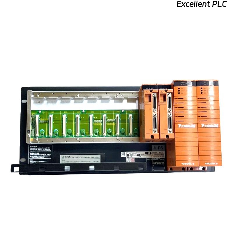
The Yokogawa SNB10D-225/CU2N Safety Node Unit acts as an interface between distributed safety I/O modules and the Safety Control Unit. It supports redundant ESB Bus communication and provides a reliable platform for high-availability SIS architectures.
SNB10D-225/CU2N Safety System Applications
- Emergency Shutdown Systems
- Gas Compression Facilities
- Refinery Safety Platforms
- Pipeline Protection Systems
- Petrochemical Safety Instrumented Systems
Project Planning Before Installation
Successful Commissioning begins during engineering design.
- Determine node quantities
- Calculate I/O capacity
- Review redundancy strategy
- Allocate safety loops
- Plan communication topology
ESB Bus Network Design Considerations
- Node addressing strategy
- Fiber route planning
- Redundant path separation
- Network loading calculations
- Future expansion capability
Power Architecture Requirements
- Independent power feeders
- Redundant power design
- Voltage stability verification
- Circuit protection coordination
Stable power quality reduces communication-related alarms during startup.
Control Cabinet Preparation
- Rack mounting readiness
- Cable management installation
- Ground bar inspection
- Ventilation verification
Pre-Installation Inspection
- Model verification
- Connector inspection
- Visual damage assessment
- Documentation review
- Accessory verification
SNB10D-225/CU2N Installation Guide
- Disconnect cabinet power.
- Prepare installation location.
- Install the Safety Node Unit.
- Tighten mounting hardware.
- Inspect mechanical alignment.
- Verify installation integrity.
Communication Wiring Setup
- Verify ESB Bus connections
- Inspect communication ports
- Validate redundancy routing
- Confirm cable labeling
- Check connector seating
Safety I/O Integration
- Digital input assignment
- Digital output mapping
- Analog signal allocation
- Shutdown loop configuration
- Voting logic distribution
Grounding and EMC Practices
- Protective earth verification
- Shield continuity testing
- Cabinet bonding validation
- EMI reduction measures
Hardware Verification Process
- LED status inspection
- Communication health check
- Node recognition verification
- Power redundancy review
SNB10D-225/CU2N Setup Procedure
POWER ON NODE
VERIFY STATUS LEDS
CHECK ESB COMMUNICATION
CONFIRM I/O RECOGNITION
SAVE PARAMETERS
STORE BACKUP CONFIGURATION
System Configuration Validation
- Node address review
- I/O mapping verification
- Communication parameter validation
- Logic assignment review
- Redundancy parameter inspection
Commissioning Workflow
Field engineers typically verify communication infrastructure before executing safety loop testing.
- Hardware verification.
- Communication validation.
- Redundancy testing.
- Signal simulation.
- Integrated SIS testing.
Safety Function Testing
- Input simulation testing
- Output response verification
- Alarm functionality checks
- Trip logic validation
- Recovery testing
Performance Optimization
- Baseline communication monitoring
- Network latency tracking
- Configuration backup management
- Periodic redundancy testing
Real Commissioning Case
During commissioning of a refinery expansion project, one SNB10D-225/CU2N repeatedly generated communication alarms.
Observed values included:
- Supply voltage: 119.1 VAC
- Communication latency: 176 ms
- Node status: Healthy
- I/O visibility: Partial
Initial investigation focused on the Safety Node Unit itself.
However, engineers discovered that one redundant ESB Bus path had been connected to the wrong network segment.
After correcting the communication path:
- Latency dropped to 10 ms
- Communication stabilized
- All I/O modules became visible
- Commissioning completed without further alarms
We observed that network design errors often appear identical to hardware faults during startup.
SNB10D-225/CU2N Installation Guide FAQ
What is the primary role of the SNB10D-225/CU2N?
It provides communication and power distribution between safety I/O modules and the Safety Control Unit within a redundant SIS architecture.
Why is ESB Bus validation important during Setup?
Most startup communication issues originate from addressing, topology, or routing errors rather than hardware failures.
Should redundancy testing be completed before loop testing?
Yes. Infrastructure validation should always be completed before safety function verification.
Summary: Successful SNB10D-225/CU2N Installation, Setup, and Commissioning depend on accurate System Configuration, robust ESB Bus design, disciplined redundancy testing, and comprehensive communication verification.