 Excellent PLC


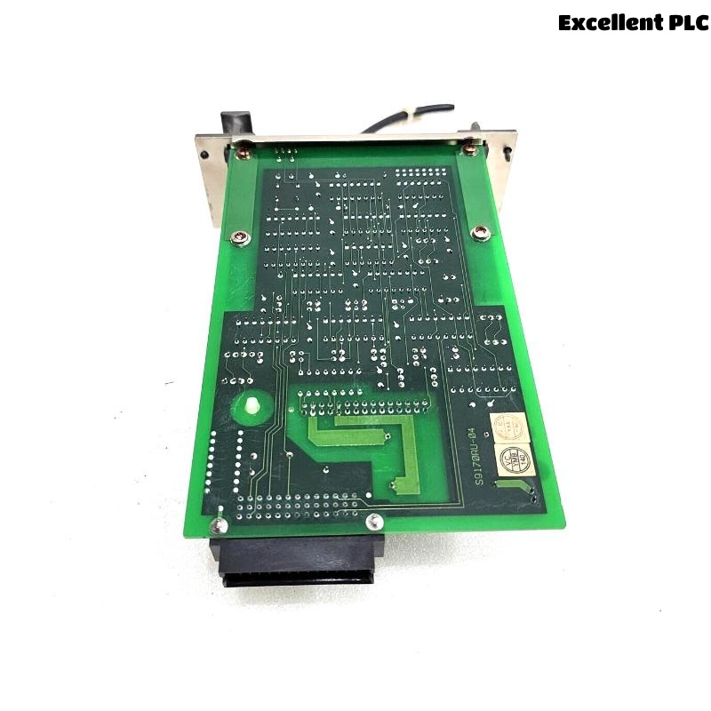
The Yokogawa AIP571 Electrical Transceiver RIO I/O Module is an optical communication interface used in Yokogawa CENTUM CS and CENTUM VP Distributed Control Systems (DCS). It converts electrical communication signals into optical signals for transmission between the Field Control Unit (FCU) and Remote I/O (RIO) stations over fiber-optic networks. By providing long-distance, noise-immune communication, the AIP571 ensures reliable exchange of process data in demanding industrial environments. Communication failures involving the AIP571 can lead to Remote I/O loss, field signal interruptions, controller alarms, or process downtime. A systematic troubleshooting procedure enables maintenance engineers to identify the root cause quickly and restore stable communication.
Contents
- 1. Understanding Fiber Communication Faults
- 2. Common Failure Symptoms
- 3. Typical Causes of Communication Failures
- 4. Initial Hardware Inspection
- 5. Power Supply Verification
- 6. Optical Fiber Diagnostics
- 7. Communication Configuration Verification
- 8. Diagnostic Analysis
- 9. Recommended Troubleshooting Workflow
- 10. Corrective Actions
- 11. Communication Recovery Verification
- 12. Preventive Maintenance
- 13. Real Industrial Maintenance Case
- 14. Frequently Asked Questions
Understanding Fiber Communication Faults
The AIP571 serves as the optical communication bridge between the FCU and Remote I/O stations. Most communication failures originate from contaminated fiber connectors, damaged optical cables, incorrect TX/RX connections, configuration errors, or Remote I/O power issues rather than internal hardware defects.
Common Failure Symptoms
- Remote I/O station is offline.
- Input and output signals are unavailable.
- Fiber communication alarms appear.
- Engineering station cannot detect the Remote I/O station.
- Intermittent process data updates.
- Communication timeout alarms.
- Status LEDs indicate communication failure.
- Controller reports Remote I/O diagnostic errors.
Typical Causes of Communication Failures
- Reversed TX and RX fiber connections.
- Dirty or contaminated fiber connectors.
- Broken or excessively bent fiber-optic cable.
- Remote I/O power supply failure.
- Incorrect communication parameters.
- Loose module installation.
- Backplane connection problems.
- Internal AIP571 hardware failure.
Initial Hardware Inspection
- Verify the module is fully seated.
- Inspect the fiber-optic ports.
- Check connector cleanliness.
- Inspect cable routing for mechanical damage.
- Verify LED indicator status.
Power Supply Verification
- Measure FCU supply voltage.
- Verify Remote I/O power supplies.
- Inspect redundant power systems if installed.
- Review controller power diagnostics.
- Correct power abnormalities before communication testing.
Optical Fiber Diagnostics
- Verify TX and RX fiber orientation.
- Clean all optical connectors using approved fiber cleaning tools.
- Inspect fiber ends for contamination or scratches.
- Measure optical signal attenuation if equipment is available.
- Replace damaged fiber-optic cables.
Communication Configuration Verification
- Verify Remote I/O station address.
- Confirm communication parameter settings.
- Review engineering database configuration.
- Verify controller communication assignments.
- Check network initialization status.
Diagnostic Analysis
| Observed Condition | Possible Diagnosis |
|---|---|
| Remote I/O offline | Fiber disconnected or Remote I/O power failure |
| No optical communication | TX/RX fibers reversed or broken |
| Intermittent communication | Dirty connector or damaged optical cable |
| Communication timeout | Signal attenuation or configuration mismatch |
| Diagnostic communication alarm | Remote I/O communication failure |
Recommended Troubleshooting Workflow
VERIFY POWER SUPPLIES
CHECK MODULE INSTALLATION
INSPECT FIBER CONNECTIONS
VERIFY TX/RX POLARITY
CLEAN OPTICAL CONNECTORS
VERIFY COMMUNICATION SETTINGS
REVIEW DIAGNOSTIC LOGS
IMPLEMENT CORRECTIVE ACTION
VERIFY SIGNAL RECOVERY
MONITOR SYSTEM OPERATION
Corrective Actions
- Reconnect loose optical connectors.
- Correct TX/RX fiber polarity.
- Clean contaminated fiber connectors.
- Replace damaged optical cables.
- Restore Remote I/O power supplies.
- Correct communication configuration.
- Replace the AIP571 only after confirming internal hardware failure.
Communication Recovery Verification
- Verify Remote I/O station recognition.
- Confirm engineering station communication.
- Verify stable process signal updates.
- Review controller diagnostics.
- Confirm all communication alarms have cleared.
Preventive Maintenance
- Clean fiber-optic connectors during scheduled maintenance.
- Inspect fiber routing and bend radius.
- Verify connector locking mechanisms.
- Monitor communication diagnostics regularly.
- Replace aging or damaged optical cables proactively.
Real Industrial Maintenance Case
During startup following a plant expansion, a newly installed Remote I/O cabinet failed to communicate with the main controller.
Investigation showed that the optical fiber connectors were clean and undamaged, but the transmit and receive fibers had been connected to the wrong ports.
After correcting the fiber polarity:
- The Remote I/O station immediately appeared online.
- All field input and output signals updated normally.
- Engineering diagnostics reported stable communication.
- No additional communication alarms occurred during extended operation.
Frequently Asked Questions
Why is the Remote I/O station offline?
The most common causes are incorrect TX/RX fiber connections, contaminated fiber connectors, damaged optical cables, or loss of Remote I/O power.
Can dirty fiber connectors interrupt communication?
Yes. Dust, oil, or scratches on optical connector end faces can significantly reduce signal quality and lead to intermittent or complete communication failure.
When should the AIP571 be replaced?
The module should only be replaced after verifying the integrity of fiber-optic cables, connector cleanliness, Remote I/O power supplies, communication configuration, and confirming an internal hardware fault through diagnostic testing.
Summary
Effective troubleshooting of the Yokogawa AIP571 Electrical Transceiver RIO I/O Module requires systematic inspection of power supplies, fiber-optic connections, TX/RX polarity, communication configuration, and controller diagnostics. Following a structured troubleshooting methodology minimizes downtime, restores reliable optical communication, and ensures dependable Remote I/O operation in Yokogawa CENTUM CS and CENTUM VP Distributed Control Systems.