 Excellent PLC


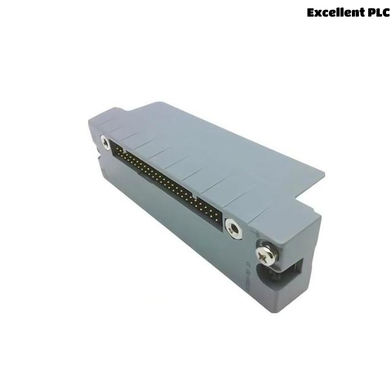
The Yokogawa ATD5A KS Cable Interface Adapter is a passive interface device used in Yokogawa CENTUM VP and CENTUM CS 3000 Distributed Control Systems (DCS). It provides the electrical connection between 32-channel digital I/O modules and KS field cables. Because the ATD5A contains no active electronic circuits, most failures are caused by connector problems, damaged KS cables, wiring errors, poor grounding, or mechanical damage. Proper troubleshooting should focus on verifying physical connections and signal continuity before replacing the adapter.
Contents
- 1. Understanding Interface Adapter Faults
- 2. Common Failure Symptoms
- 3. Typical Causes
- 4. Initial Inspection
- 5. KS Cable Verification
- 6. Connector Inspection
- 7. Diagnostic Analysis
- 8. Recommended Troubleshooting Workflow
- 9. Corrective Actions
- 10. Functional Recovery Verification
- 11. Preventive Maintenance
- 12. Industrial Maintenance Case
- 13. Frequently Asked Questions
Understanding Interface Adapter Faults
The ATD5A acts solely as a connection interface between digital I/O modules and KS field cables. Since it is a passive component, electrical failures are uncommon. Operational problems are generally associated with loose connectors, damaged KS cables, bent connector pins, poor cable routing, incorrect channel wiring, contamination, or vibration that affects connector engagement.
Common Failure Symptoms
- Multiple digital input channels are unavailable.
- Digital outputs fail to operate field devices.
- Intermittent digital signals.
- Unexpected field alarms.
- Communication appears normal but field signals are missing.
- Random channel failures.
- DCS diagnostic alarms on connected I/O modules.
- Signal loss after maintenance activities.
Typical Causes
- Loose KS cable connector.
- Damaged KS cable.
- Bent connector pins.
- Incomplete connector insertion.
- Incorrect cable routing.
- Poor grounding or shielding.
- Mechanical damage to the adapter housing.
- Field wiring errors.
Initial Inspection
- Disconnect cabinet power before inspection.
- Inspect the ATD5A housing for damage.
- Check all connector locking mechanisms.
- Inspect KS cable condition.
- Verify cabinet grounding.
- Review DCS diagnostic information.
KS Cable Verification
- Inspect cable insulation.
- Measure cable continuity.
- Verify connector orientation.
- Confirm cable identification.
- Inspect cable routing.
- Check for excessive cable tension.
Connector Inspection
- Inspect connector pins for bending.
- Verify connectors are fully seated.
- Check connector locking tabs.
- Remove dust or contamination.
- Inspect connector housings.
- Replace damaged connectors if necessary.
Diagnostic Analysis
| Observed Condition | Possible Diagnosis |
|---|---|
| Multiple channels unavailable | Loose KS cable or connector |
| Intermittent digital signals | Poor connector engagement or vibration |
| Random channel failures | Damaged cable or bent connector pins |
| No field response | Incorrect wiring or disconnected cable |
| Frequent communication alarms | Connector contamination or damaged interface |
Recommended Troubleshooting Workflow
CHECK DCS DIAGNOSTICS
INSPECT ADAPTER
VERIFY CONNECTOR LOCKING
CHECK KS CABLE
TEST CABLE CONTINUITY
VERIFY FIELD WIRING
TEST DIGITAL CHANNELS
CONFIRM NORMAL OPERATION
Corrective Actions
- Reconnect loose KS cables.
- Replace damaged KS cables.
- Straighten or replace bent connector pins.
- Correct field wiring errors.
- Clean contaminated connectors.
- Improve cable routing.
- Restore proper grounding.
- Replace the ATD5A if mechanical damage prevents reliable connections.
Functional Recovery Verification
- Verify all digital channels operate normally.
- Confirm connector engagement.
- Review DCS diagnostics.
- Test field device operation.
- Inspect cable routing.
- Monitor long-term signal stability.
Preventive Maintenance
- Inspect connectors periodically.
- Verify KS cable integrity.
- Maintain clean connector surfaces.
- Inspect cable routing.
- Check connector locking mechanisms.
- Perform scheduled continuity testing.
Industrial Maintenance Case
Following scheduled maintenance at a petrochemical facility, operators observed that eight digital input channels connected through an ATD5A adapter were no longer responding. Inspection found that the KS cable connector had not been fully locked after cabinet servicing.
After reconnecting the KS cable, verifying connector engagement, checking cable continuity, and confirming field signal operation:
- All digital input channels resumed normal operation.
- DCS diagnostic alarms cleared automatically.
- Field devices communicated reliably with the controller.
- No hardware replacement was required.
Frequently Asked Questions
Can the ATD5A generate electronic failures?
No. The ATD5A is a passive interface adapter without active electronic components. Most problems originate from connectors, KS cables, or field wiring.
Why do several digital channels fail simultaneously?
This usually indicates a loose KS cable connector, damaged cable, connector pin damage, or incorrect interface installation rather than an internal adapter failure.
When should the ATD5A be replaced?
The adapter should be replaced if the connector housing is cracked, connector retention is damaged, pins cannot maintain reliable contact, or physical damage prevents secure installation.
Summary
Effective troubleshooting of the Yokogawa ATD5A KS Cable Interface Adapter focuses on connector integrity, KS cable condition, wiring continuity, grounding, and mechanical installation. Routine inspection and proper cable management ensure reliable digital signal transmission and long-term performance in Yokogawa CENTUM Distributed Control Systems.