 Excellent PLC


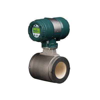
The Yokogawa AXF040C AXF Electromagnetic Flowmeter is a high-performance magnetic flowmeter designed to accurately measure the flow of electrically conductive liquids in industrial process applications. It uses Faraday’s Law of Electromagnetic Induction to provide highly stable flow measurements without moving parts. Although the AXF040C offers advanced self-diagnostic functions and excellent long-term reliability, improper installation, grounding problems, process conditions, electrical interference, or sensor failures may result in inaccurate measurements, unstable outputs, communication faults, or diagnostic alarms. A systematic troubleshooting procedure can quickly identify the root cause and restore normal operation.
Contents
- 1. Understanding Flowmeter Faults
- 2. Common Failure Symptoms
- 3. Typical Causes
- 4. Initial Inspection
- 5. Process Condition Verification
- 6. Electrical Inspection
- 7. Diagnostic Analysis
- 8. Recommended Troubleshooting Workflow
- 9. Corrective Actions
- 10. Functional Recovery Verification
- 11. Preventive Maintenance
- 12. Industrial Maintenance Case
- 13. Frequently Asked Questions
Understanding Flowmeter Faults
The AXF040C measures conductive liquid flow by detecting the voltage generated when the process fluid moves through a magnetic field. Measurement errors can occur if the measuring tube is not completely full, electrical conductivity is insufficient, grounding is inadequate, electrodes become coated, air bubbles enter the pipeline, excessive vibration is present, or electrical noise affects the signal. Internal diagnostics can help distinguish between process-related issues and hardware faults.
Common Failure Symptoms
- Flow indication remains at zero.
- Flow readings fluctuate continuously.
- Measured flow is inaccurate.
- Output signal is unstable.
- Diagnostic alarm is displayed.
- Communication with the control system fails.
- Reverse flow indication appears unexpectedly.
- Analog output does not correspond to actual flow.
Typical Causes
- Pipeline not completely full.
- Low liquid conductivity.
- Poor grounding.
- Electrode contamination or scaling.
- Air bubbles inside the measuring tube.
- Incorrect configuration parameters.
- Damaged signal wiring.
- Electrical interference.
- Internal sensor or converter fault.
Initial Inspection
- Verify power supply voltage.
- Inspect the flowmeter housing.
- Review diagnostic messages.
- Inspect wiring connections.
- Check grounding conductors.
- Verify communication status.
Process Condition Verification
- Confirm the pipeline is completely filled with liquid.
- Verify flow direction matches installation markings.
- Inspect for trapped air.
- Confirm adequate liquid conductivity.
- Check upstream and downstream piping conditions.
- Inspect for excessive pipeline vibration.
Electrical Inspection
- Verify power supply stability.
- Inspect signal cable shielding.
- Measure grounding resistance.
- Inspect communication wiring.
- Verify analog output signals.
- Check connector integrity.
Diagnostic Analysis
| Observed Condition | Possible Diagnosis |
|---|---|
| No flow indication | Empty pipeline, wiring fault, or power supply problem |
| Unstable flow measurement | Air bubbles, poor grounding, or electrical interference |
| Measurement offset | Incorrect configuration or electrode contamination |
| Communication failure | Communication cable or configuration fault |
| Diagnostic alarm active | Internal self-diagnostic warning or process abnormality |
Recommended Troubleshooting Workflow
CHECK DIAGNOSTIC MESSAGES
VERIFY POWER SUPPLY
CONFIRM PIPELINE IS FULL
CHECK GROUNDING
INSPECT WIRING
VERIFY CONFIGURATION
TEST OUTPUT SIGNALS
CONFIRM NORMAL OPERATION
Corrective Actions
- Restore normal pipeline filling conditions.
- Improve grounding.
- Clean measuring electrodes.
- Remove trapped air from the pipeline.
- Correct configuration parameters.
- Replace damaged cables.
- Repair communication wiring.
- Replace the sensor or converter if internal failure is confirmed.
Functional Recovery Verification
- Verify stable flow indication.
- Compare measurements with a calibrated reference.
- Confirm analog output accuracy.
- Verify digital communication.
- Review diagnostic information.
- Monitor long-term measurement stability.
Preventive Maintenance
- Inspect grounding regularly.
- Check cable connections.
- Clean electrodes when process conditions require.
- Verify calibration periodically.
- Inspect process piping.
- Review self-diagnostic history.
Industrial Maintenance Case
At a wastewater treatment plant, operators reported unstable flow measurements from an AXF040C installed on a recycled water pipeline. Inspection showed that air entered the pipeline after a nearby pump modification, causing intermittent empty-pipe conditions. In addition, one grounding strap had become loose.
After removing trapped air, restoring continuous pipeline filling, tightening the grounding connection, and verifying output calibration:
- Flow readings became stable.
- Analog output matched the reference flow value.
- Diagnostic alarms cleared automatically.
- The flowmeter resumed accurate long-term operation.
Frequently Asked Questions
Why does the AXF040C indicate zero flow while liquid is flowing?
Possible causes include an empty measuring tube, insufficient liquid conductivity, wiring problems, power supply faults, or incorrect configuration.
Why are the flow readings unstable?
Unstable measurements are commonly caused by air bubbles, poor grounding, electrical interference, excessive vibration, or contaminated electrodes.
When should the AXF040C be recalibrated?
Calibration should be verified during scheduled maintenance, after major process changes, or whenever measurement accuracy is questioned following inspection of installation and process conditions.
Summary
Effective troubleshooting of the Yokogawa AXF040C AXF Electromagnetic Flowmeter requires systematic verification of process conditions, grounding, electrical wiring, configuration parameters, communication status, and diagnostic information. Routine preventive maintenance and proper installation practices ensure accurate flow measurement and reliable long-term performance in industrial process control systems.