

Table of Contents
- 21505-00-12-05-02 Installation Overview
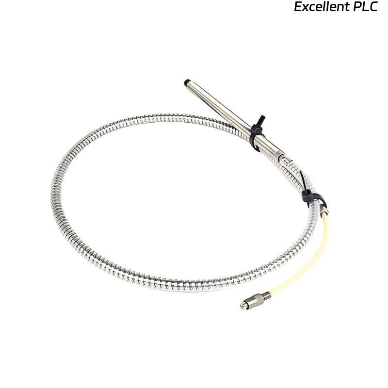
- 7200 8 mm Armored Probe Application
- Pre-Installation Inspection and Preparation
- Probe Mounting and Armored Cable Handling
- Gap Calibration and Signal Adjustment
- Monitoring System Integration and Wiring
- Commissioning Validation and Dynamic Testing
- Real Installation Experience
- Installation FAQ
- Final Engineering Summary
21505-00-12-05-02 Installation Overview
Bently Nevada 21505-00-12-05-02 7200 8 mm armored standard mount probe installation quality determines the stability of shaft displacement monitoring and machine protection reliability. In many industrial applications, incorrect armored cable handling creates unstable vibration signals during startup and load changes.
This Installation Guide explains practical Setup methods for probe alignment, armored cable routing, signal calibration, and vibration monitoring Commissioning.
7200 8 mm Armored Probe Application
- Monitors radial shaft vibration and displacement
- Supports turbine and compressor protection systems
- Provides stable operation in harsh environments
- Interfaces with PLC Controller and monitoring modules
Pre-Installation Inspection and Preparation
- Inspect armored cable for transportation damage
- Verify shaft target surface condition
- Check mounting bracket rigidity
- Ensure sufficient cable bending clearance
Probe Mounting and Armored Cable Handling
- Install probe perpendicular to shaft surface
- Secure armored cable near probe housing
- Avoid excessive cable tension and sharp bending
- Prevent vibration transfer through unsupported cable sections
  // Mounting Validation
  IF Cable_Tension > Allowable_Limit THEN
      Risk_Of_Signal_Instability = TRUE;
  ELSE
      Continue_Gap_Calibration();
  END_IF;
Gap Calibration and Signal Adjustment
- Adjust probe position until gap voltage reaches operating range
- Recommended voltage: -8V to -10V
- Observe waveform stability during shaft rotation
- Record baseline vibration values for future Troubleshooting
Monitoring System Integration and Wiring
- Route signal cable separately from power cables
- Maintain shielding continuity throughout installation
- Verify grounding at monitoring rack
- Check System Configuration and alarm scaling
Commissioning Validation and Dynamic Testing
- Monitor signal noise during startup
- Observe displacement trend during load increase
- Check thermal influence on gap voltage
- Validate alarm and shutdown response
Real Installation Experience
During commissioning of a refinery compressor, repeated displacement alarms occurred after several hours of operation:
- Gap voltage fluctuated between -9V and -6.7V
- Signal spikes appeared during load transitions
We observed that the armored cable was unsupported near the machine frame and vibrated continuously.
After corrective actions:
- Installed additional cable clamps
- Recalibrated probe gap
Result:
- Stable vibration monitoring restored
- False alarms eliminated
Installation FAQ
Why must armored cables be properly supported?
Unsupported cables can transfer mechanical vibration into the probe assembly and affect signal stability.
What is the normal operating gap voltage?
Most systems operate reliably between -8V and -10V DC.
Can poor cable routing affect vibration readings?
Yes. Incorrect routing near high-power wiring may introduce EMI interference.
Final Engineering Summary
The Bently Nevada 21505-00-12-05-02 Installation Guide highlights that reliable vibration monitoring depends on stable probe mounting, proper armored cable routing, and accurate System Configuration.