

Table of Contents
- 24701-16-10-00-037-00-01 Installation Overview
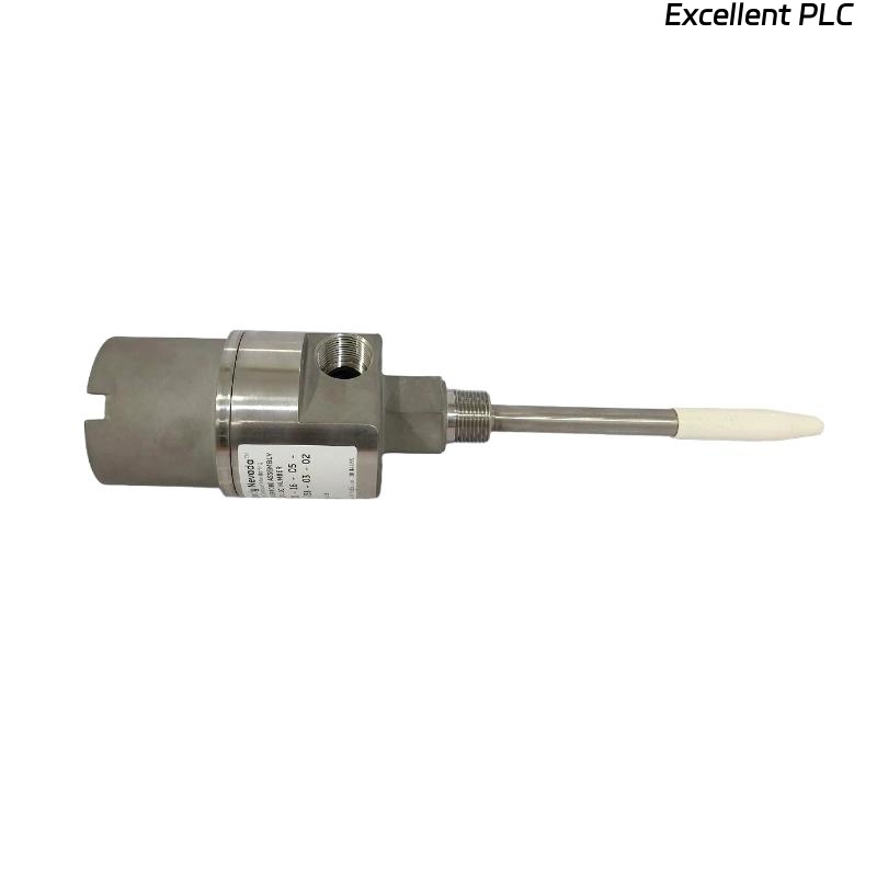
- 3300XL Proximity Probe Housing Assembly Function
- Technical Configuration and Ordering Code
- Mechanical Inspection Before Installation
- Housing Assembly Mounting Procedure
- Probe Cable Routing and Shielding Requirements
- Commissioning and Gap Voltage Verification
- Signal Stability Optimization Methods
- Real Turbine Installation Experience
- Installation FAQ
- Final Engineering Summary
24701-16-10-00-037-00-01 Installation Overview
Bently Nevada 24701-16-10-00-037-00-01 3300XL proximity probe housing assembly installation quality directly affects shaft vibration monitoring accuracy and machinery protection reliability. Improper housing alignment, weak mounting structures, and incorrect probe routing frequently create unstable vibration signals and intermittent alarms in rotating machinery systems.
This Installation Guide explains practical Setup methods for housing assembly installation, probe adjustment, signal cable routing, and machinery monitoring Commissioning.
3300XL Proximity Probe Housing Assembly Function
- Supports external mounting of 3300 XL 8 mm proximity probes
- Provides probe protection in harsh industrial environments
- Allows external probe adjustment and maintenance access
- Supports shaft vibration and displacement monitoring systems
Technical Configuration and Ordering Code
- Model: 24701 Proximity Probe Housing Assembly
- Probe Option: 16 = 3300 XL 8 mm probe
- Probe Cable Length: 10 = 1.0 metre (39 in)
- Standoff Adapter: 00 = No standoff adapter
- Probe Penetration: 037 = 3.7 in
- Mounting Thread Option: 01
The 24701 housing assemblies are designed for 3300 XL proximity transducer systems and support external probe adjustment and maintenance access for rotating machinery applications. :contentReference[oaicite:0]{index=0}
Mechanical Inspection Before Installation
- Inspect housing threads and sealing surfaces
- Verify probe alignment with shaft target surface
- Check mounting rigidity and vibration resistance
- Inspect O-rings and sealing components before assembly
Housing Assembly Mounting Procedure
Proper housing alignment is essential for stable shaft vibration monitoring and long-term probe reliability.
- Install the housing using the specified mounting thread
- Align probe perpendicular to shaft target surface
- Adjust probe penetration to recommended operating gap
- Secure all fittings and cable seals before startup
  // Probe Gap Verification Logic
  IF Gap_Voltage < -8V OR Gap_Voltage > -10V THEN
      Adjust_Probe_Position();
  ELSE
      Continue_System_Commissioning();
  END_IF;
Probe Cable Routing and Shielding Requirements
- Separate probe cables from inverter and motor power wiring
- Maintain shielding continuity at all cable connections
- Secure extension cables near the housing assembly
- Verify proper grounding continuity before startup
Commissioning and Gap Voltage Verification
- Observe waveform stability during startup
- Verify gap voltage at operating speed
- Monitor shaft displacement trend behavior
- Validate alarm and shutdown response logic
Signal Stability Optimization Methods
- Improve bracket rigidity near the housing assembly
- Reduce EMI exposure near signal cables
- Inspect waveform harmonics during acceleration
- Record baseline vibration data after commissioning
Real Turbine Installation Experience
During commissioning of a steam turbine vibration monitoring system, unstable shaft displacement readings appeared during acceleration:
- Gap voltage drifted from -9.2V to -6.1V
- Waveform spikes increased during load changes
Investigation revealed that the housing mounting bracket experienced thermal movement during operation.
After corrective actions:
- Improved bracket rigidity
- Adjusted housing alignment and cable support routing
Result:
- Stable shaft monitoring restored
- False vibration alarms eliminated
Installation FAQ
Why is probe housing alignment important?
Incorrect housing alignment may create unstable shaft displacement readings and inaccurate monitoring signals.
Can thermal expansion affect housing assembly performance?
Yes. Thermal movement may alter probe alignment and gap voltage stability.
Should probe cables be separated from inverter wiring?
Yes. Proper cable separation reduces EMI interference and improves signal integrity.
Final Engineering Summary
The Bently Nevada 24701-16-10-00-037-00-01 Installation Guide demonstrates that reliable machinery monitoring depends on accurate housing Setup, stable mounting structures, proper shielding continuity, and optimized System Configuration.