

Table of Contents
- AAM10-S1 Installation Overview
- Current/Voltage Input Module Function
- AAM10-S1 Functional Features
- Pre-Installation Inspection Procedure
- Module Installation and Rack Mounting
- Analog Signal Wiring Requirements
- Signal Configuration and DCS Integration
- Industrial Automation Commissioning
- Signal Stability Optimization
- Industrial Application Example
- Installation FAQ
- Engineering Summary
AAM10-S1 Installation Overview
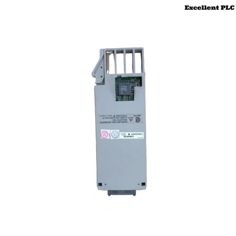
The YOKOGAWA AAM10-S1 is an industrial analog current and voltage input module designed for Yokogawa CENTUM distributed control systems (DCS). The module is used for process signal acquisition, industrial analog input monitoring, transmitter integration, and stable current/voltage measurement in industrial automation systems.
Proper installation directly affects analog signal accuracy, DCS monitoring reliability, and process automation stability. Incorrect grounding continuity, unstable cabinet power supplies, and improper analog cable routing can create signal fluctuation, measurement drift, and unstable process monitoring conditions.
Current/Voltage Input Module Function
- Receives industrial analog current and voltage signals
- Supports transmitter and field instrumentation integration
- Provides centralized analog signal acquisition
- Interfaces field devices with DCS controllers
- Supports stable industrial process monitoring
AAM10-S1 Functional Features
- Industrial analog current/voltage acquisition architecture
- Compatible with Yokogawa CENTUM VP and CS systems
- Supports high-reliability process signal monitoring
- Optimized for industrial automation environments
- Designed for stable long-term DCS operation
Vendor references identify the AAM10-S1 as a Yokogawa analog current and voltage input module used in industrial process automation and distributed control system applications.
Pre-Installation Inspection Procedure
- Inspect module housing and terminal connectors
- Verify stable cabinet DC power distribution
- Check grounding continuity throughout the cabinet
- Inspect shielded analog signal cable integrity
- Verify cabinet cooling airflow and operating conditions
Module Installation and Rack Mounting
Proper installation is essential for maintaining stable analog signal acquisition and long-term industrial automation reliability.
- Install the AAM10-S1 securely into the designated rack slot
- Verify proper backplane connector engagement
- Maintain adequate airflow around the module
- Inspect signal terminals before startup
  // Analog Input Startup Logic
  IF Cabinet_Power_OK = TRUE THEN
      Initialize_AAM10S1_Module();
      Verify_Analog_Input_Status();
  ELSE
      Inspect_DC_Power_System();
  END_IF;
Analog Signal Wiring Requirements
- Use shielded twisted-pair analog signal cables
- Separate analog signal wiring from inverter and motor cables
- Maintain proper grounding continuity
- Verify terminal tightness before startup
- Ground cable shielding at one side only
Industrial analog signal systems require shielded wiring and proper grounding practices to minimize EMI interference and maintain stable process measurement accuracy.
Signal Configuration and DCS Integration
- Configure analog current and voltage scaling parameters
- Verify transmitter signal ranges
- Inspect DCS communication stability
- Validate stable analog process measurements
Industrial Automation Commissioning
- Observe analog signal stability during startup
- Verify measurement accuracy across all channels
- Check module diagnostic indicators
- Validate stable DCS process monitoring conditions
Signal Stability Optimization
- Improve cabinet grounding continuity integrity
- Reduce EMI exposure near analog signal wiring
- Maintain stable cabinet operating temperatures
- Record baseline process signal calibration values
Industrial Application Example
During startup of a refinery automation system, unstable analog current measurements appeared intermittently:
- DCS operator stations displayed fluctuating process values
- Signal instability increased during heavy motor startup
Investigation identified:
- Analog signal cables routed beside inverter power wiring
- Improper cabinet grounding continuity
After corrective actions:
- Separated analog and high-voltage cable routing
- Improved grounding continuity integrity
Result:
- Stable analog signal acquisition restored
- DCS monitoring reliability improved significantly
Installation FAQ
What is the primary function of the AAM10-S1?
The AAM10-S1 is used for industrial analog current and voltage signal acquisition in Yokogawa DCS systems.
Why is shield grounding important?
Proper shield grounding minimizes EMI interference and improves analog signal stability.
Can analog signal cables be routed beside inverter wiring?
No. Analog signal wiring should be separated from high-voltage and inverter cables to reduce electrical interference.
Engineering Summary
The YOKOGAWA AAM10-S1 Installation Guide demonstrates that reliable analog signal acquisition depends on stable cabinet power distribution, proper grounding continuity, optimized shielded cable routing, and disciplined DCS commissioning procedures.