

Table of Contents
- F3XH04-3N Installation Overview
- High-Speed Input Module Function
- F3XH04-3N Functional Features
- Technical Specifications
- Pre-Installation Inspection Procedure
- Rack Mounting and Electrical Installation
- High-Speed Signal Wiring Requirements
- PLC Configuration and Signal Setup
- Industrial Signal Commissioning
- Signal Stability Optimization
- Industrial Application Example
- Installation FAQ
- Engineering Summary
F3XH04-3N Installation Overview
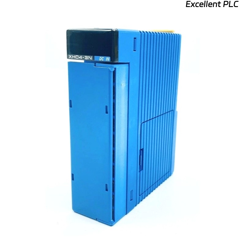
The YOKOGAWA F3XH04-3N is a high-speed digital input module designed for Yokogawa FA-M3 PLC and industrial automation systems. The module supports high-speed pulse acquisition, fast signal detection, interrupt processing, and industrial encoder or sensor input applications.
Proper installation directly affects signal acquisition accuracy, PLC response performance, and industrial automation reliability. Incorrect grounding continuity, unstable 24V DC power supplies, and improper signal cable routing can create pulse loss, false triggering, and unstable high-speed signal processing.
High-Speed Input Module Function
- Acquires high-speed industrial pulse signals
- Supports encoder and sensor signal processing
- Provides interrupt and pulse-catch functionality
- Supports fast PLC automation response
- Improves industrial machine control accuracy
F3XH04-3N Functional Features
- 4-point independent high-speed DC inputs
- 24V DC high-speed signal processing
- Pulse-catch and interrupt functionality
- 50μs minimum pulse width support
- Photo-coupler isolated industrial inputs
Technical Specifications
- Input type: DC voltage
- Number of inputs: 4
- Rated input voltage: 24V DC
- Operating voltage range: 20.4–26.4V DC
- Input response time: 50μs maximum
- Minimum pulse width: 50μs
- Isolation method: Photo-coupler isolation
- Input impedance: 2.1kΩ
Yokogawa documentation identifies the F3XH04-3N as a 4-point 24V DC high-speed input module supporting pulse-catch and interrupt functions for FA-M3 PLC systems.
Pre-Installation Inspection Procedure
- Inspect module housing and terminal integrity
- Verify stable 24V DC power distribution
- Check grounding continuity throughout the PLC cabinet
- Inspect encoder and sensor signal cable integrity
- Verify cabinet ventilation and environmental conditions
Rack Mounting and Electrical Installation
Proper installation is essential for maintaining stable high-speed signal acquisition and long-term PLC reliability.
- Install the F3XH04-3N securely into the designated PLC rack slot
- Verify module connector engagement
- Maintain adequate airflow around the module
- Inspect all signal and power connections before startup
  // High-Speed Input Startup Logic
  IF PLC_Power_OK = TRUE THEN
      Initialize_F3XH04_3N_Module();
      Verify_HighSpeed_Input_Status();
  ELSE
      Inspect_24VDC_Power_System();
  END_IF;
High-Speed Signal Wiring Requirements
- Use shielded twisted-pair signal cables
- Separate encoder and sensor wiring from inverter power cables
- Maintain proper grounding continuity
- Verify signal terminal tightness
- Ground shielding according to industrial instrumentation standards
High-speed industrial signal systems require shielded wiring and disciplined grounding practices to minimize EMI interference and maintain accurate pulse acquisition performance.
PLC Configuration and Signal Setup
- Configure pulse-catch functionality using DIP switches
- Set interrupt processing parameters
- Verify PLC ladder logic signal processing
- Validate stable high-speed input detection
Industrial Signal Commissioning
- Observe pulse signal stability during startup
- Verify interrupt response performance
- Check module LED diagnostic indicators
- Validate stable PLC signal acquisition
Signal Stability Optimization
- Improve cabinet grounding continuity integrity
- Reduce EMI exposure near signal wiring
- Maintain stable cabinet operating temperatures
- Record baseline pulse signal conditions
Industrial Application Example
During commissioning of a packaging machine encoder system, intermittent pulse loss appeared at high conveyor speeds:
- Encoder pulse counts became unstable
- Machine synchronization errors increased during motor acceleration
Investigation identified:
- Encoder signal wiring routed beside inverter motor cables
- Improper PLC cabinet grounding continuity
After corrective actions:
- Separated encoder and high-voltage cable routing
- Improved cabinet grounding continuity
Result:
- Stable high-speed pulse acquisition restored
- Machine synchronization reliability improved significantly
Installation FAQ
What is the primary function of the F3XH04-3N?
The F3XH04-3N acquires high-speed industrial pulse and sensor signals for PLC automation systems.
What is the minimum supported pulse width?
The module supports a minimum pulse width of 50μs.
Why are shielded signal cables important?
Shielded signal cables reduce EMI interference and improve high-speed pulse acquisition accuracy.
Engineering Summary
The YOKOGAWA F3XH04-3N Installation Guide demonstrates that reliable high-speed PLC signal acquisition depends on stable 24V DC power distribution, proper grounding continuity, optimized signal wiring practices, and disciplined PLC commissioning procedures.