

Table of Contents
- VI702 Installation Overview
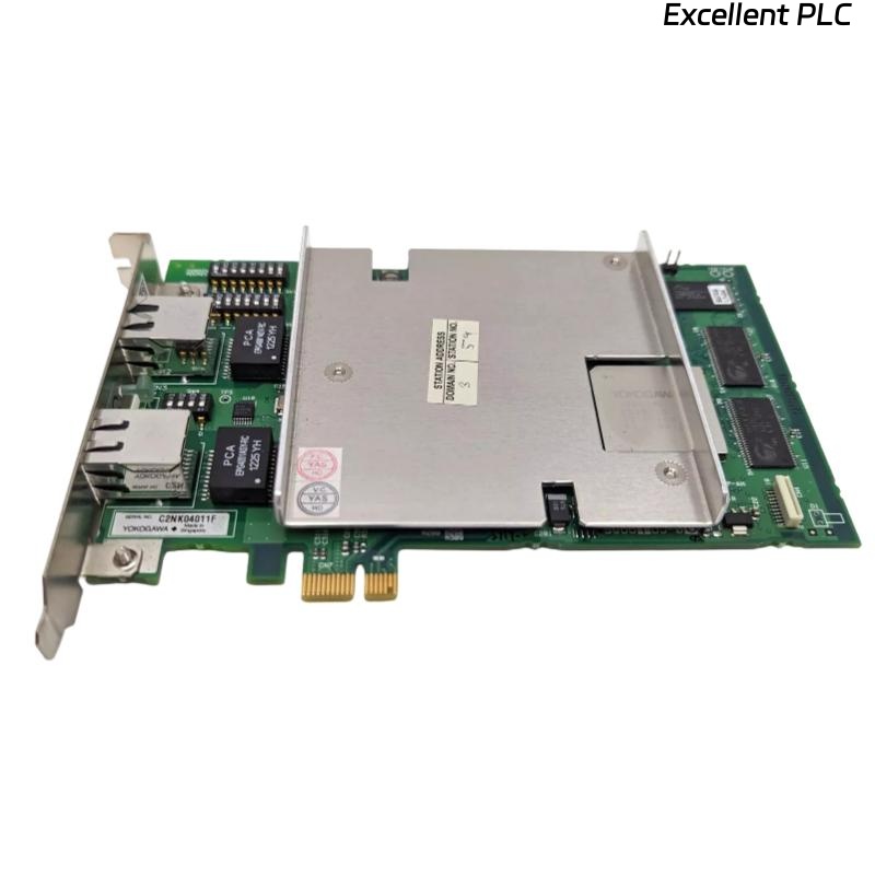
- Interface Card Function
- VI702 Functional Features
- Pre-Installation Inspection Procedure
- Module Installation and Rack Mounting
- Signal Wiring and Communication Connection Requirements
- System Configuration and Interface Setup
- Communication System Commissioning
- Signal Stability Optimization Methods
- Real Industrial Communication Application
- Installation FAQ
- Final Engineering Summary
VI702 Installation Overview
YOKOGAWA VI702 interface card installation quality directly affects industrial control system communication stability and I/O data transmission reliability. Incorrect module installation, unstable grounding continuity, and improper communication wiring frequently create intermittent communication faults and unstable controller data exchange in industrial automation systems.
This Installation Guide explains practical Setup methods for interface card installation, signal wiring inspection, communication configuration, and industrial automation Commissioning.
Interface Card Function
- Provides communication interface functions for industrial control systems
- Supports I/O signal transmission and system integration
- Enables controller and field device communication
- Supports industrial automation network connectivity
VI702 Functional Features
- Industrial-grade communication interface architecture
- High-reliability signal processing capability
- Modular control system integration support
- Stable operation in industrial environments
- Designed for distributed control system applications
The YOKOGAWA VI702 interface card is designed for industrial automation systems requiring reliable communication, stable signal transmission, and long-term operational stability in demanding process environments.
Pre-Installation Inspection Procedure
- Inspect interface card connectors and edge contacts
- Verify module compatibility with the control rack
- Check grounding continuity and cabinet ventilation
- Inspect communication wiring integrity before installation
Module Installation and Rack Mounting
Proper module installation is essential for stable communication performance and long-term industrial automation reliability.
- Insert the interface card securely into the designated rack slot
- Verify connector engagement and locking mechanisms
- Maintain adequate airflow around installed modules
- Inspect backplane connection stability before energizing
  // Interface Card Startup Verification
  IF Power_Supply_Stable = TRUE THEN
      Initialize_Interface_Module();
      Verify_Communication_Status();
  ELSE
      Inspect_Power_System();
  END_IF;
Signal Wiring and Communication Connection Requirements
- Use shielded communication cables where required
- Separate communication wiring from inverter power systems
- Maintain grounding continuity throughout the control cabinet
- Inspect terminal connections before commissioning
System Configuration and Interface Setup
- Configure communication parameters and addresses
- Verify I/O mapping and signal assignments
- Check controller communication settings
- Validate interface module diagnostics
Communication System Commissioning
- Observe communication stability during startup
- Verify I/O signal transmission accuracy
- Check communication alarm and diagnostic status
- Validate controller and field device data exchange
Signal Stability Optimization Methods
- Improve grounding continuity within the control cabinet
- Reduce EMI exposure near communication wiring
- Secure communication cable routing structures
- Record baseline communication performance data
Real Industrial Communication Application
During commissioning of a refinery distributed control system, intermittent communication instability appeared between controller modules:
- I/O update delays occurred intermittently
- Communication alarms appeared during startup
Investigation revealed communication cables routed adjacent to inverter power systems and unstable grounding continuity within the control cabinet.
After corrective actions:
- Re-routed communication wiring
- Improved grounding continuity and module seating stability
Result:
- Stable communication restored
- I/O transmission reliability improved significantly
Installation FAQ
Why is grounding continuity important for interface modules?
Proper grounding continuity reduces EMI interference and improves communication stability.
Can incorrect cable routing affect interface card communication?
Yes. Communication cables routed near inverter systems may experience electrical interference.
Should interface modules be hot-swapped during operation?
Follow system maintenance procedures and verify controller support before performing module replacement operations.
Final Engineering Summary
The YOKOGAWA VI702 Installation Guide demonstrates that reliable industrial communication depends on proper module Setup, stable grounding continuity, optimized cable routing, and disciplined automation system Commissioning.