

Table of Contents
- 21747-045-00 Installation Overview
- Proximitor Extension Cable Role in Monitoring Systems
- Installation Planning and Cable Inspection
- Extension Cable Routing and EMI Prevention
- Connector Assembly and Shielding Protection
- Electrical Verification and System Configuration
- Commissioning and Signal Stability Validation
- Real Machinery Installation Experience
- Installation FAQ
- Final Engineering Summary
21747-045-00 Installation Overview
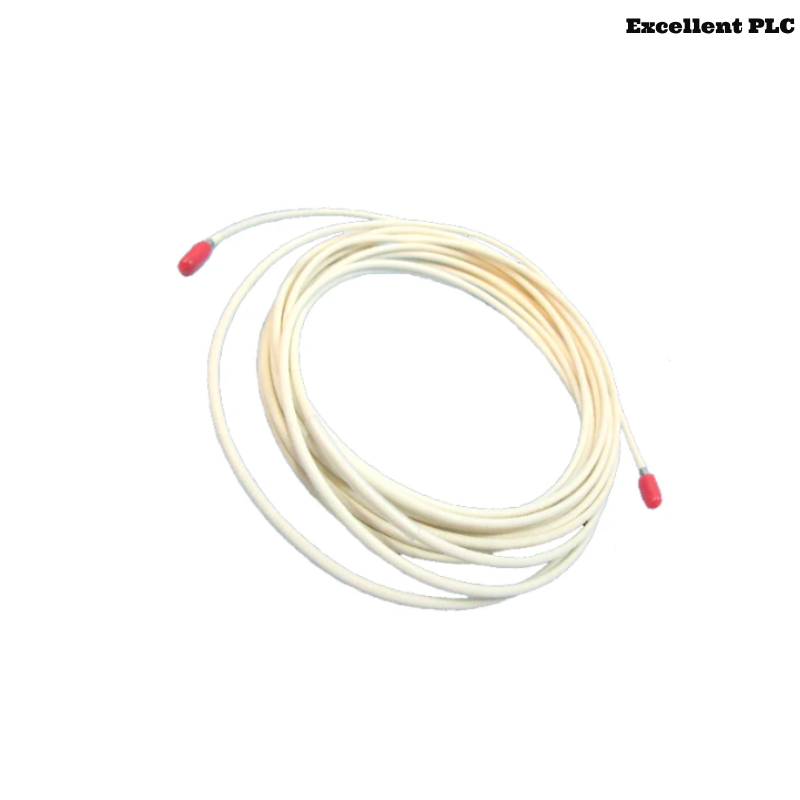
Bently Nevada 21747-045-00 proximitor probe extension cable installation quality has a direct influence on shaft vibration monitoring accuracy and machinery protection stability. In industrial turbine systems, improperly routed extension cables often create intermittent signal noise and unstable displacement readings.
This Installation Guide explains practical Setup methods for extension cable routing, shielding protection, connector installation, and vibration monitoring Commissioning.
Proximitor Extension Cable Role in Monitoring Systems
- Connects proximity probes to proximitor sensors
- Transfers shaft displacement and vibration signals
- Supports long-distance signal transmission
- Interfaces with PLC Controller and monitoring modules
Installation Planning and Cable Inspection
- Inspect cable sheath for physical damage
- Verify connector cleanliness before installation
- Check shielding continuity using electrical testing
- Confirm cable length compatibility with monitoring systems
Extension Cable Routing and EMI Prevention
- Separate signal cable from inverter power wiring
- Use grounded trays for long-distance cable routing
- Avoid sharp bending at connector points
- Secure cable to prevent vibration-induced movement
  // EMI Risk Validation
  IF Cable_Routed_Near_VFD = TRUE THEN
      EMI_Interference = HIGH;
  ELSE
      Signal_Transmission = STABLE;
  END_IF;
Connector Assembly and Shielding Protection
- Clean connectors before final assembly
- Verify secure mechanical coupling
- Protect connectors from oil and moisture ingress
- Maintain shielding continuity across all joints
Electrical Verification and System Configuration
- Check cable impedance compatibility
- Verify proximitor calibration parameters
- Confirm alarm threshold settings
- Inspect grounding continuity across the monitoring system
Commissioning and Signal Stability Validation
- Observe waveform quality during startup
- Monitor signal noise at operating speed
- Verify stable displacement trends under load
- Check long-term monitoring stability
Real Machinery Installation Experience
During commissioning of a gas turbine monitoring system, intermittent shaft displacement alarms occurred during acceleration:
- Signal spikes exceeded baseline values by approximately 34%
- Waveform distortion appeared near operating speed
We observed that the extension cable was routed in parallel with inverter power cables for more than 12 meters.
After corrective actions:
- Re-routed the extension cable through grounded isolation trays
- Improved shielding continuity at connector locations
Result:
- Stable shaft vibration monitoring restored
- False alarms eliminated during operation
Installation FAQ
Why is extension cable routing important for vibration monitoring?
Incorrect routing near high-current systems may introduce EMI interference into vibration signals.
Can connector contamination affect monitoring accuracy?
Yes. Oxidized connectors may increase signal resistance and create unstable readings.
Should extension cables be mechanically supported?
Yes. Unsupported cable movement can transfer vibration stress into connectors and monitoring systems.
Final Engineering Summary
The Bently Nevada 21747-045-00 Installation Guide demonstrates that stable extension cable routing, proper shielding continuity, and accurate System Configuration are critical for reliable machinery vibration monitoring.