

Table of Contents
- 21747-040-01 Installation Overview
- Proximitor Extension Cable Application
- Preparation Before Extension Cable Installation
- Extension Cable Routing and Mechanical Protection
- Connector Assembly and Shielding Verification
- System Configuration and Signal Matching
- Startup Validation and Commissioning Process
- Real Industrial Installation Case
- Installation FAQ
- Final Engineering Summary
21747-040-01 Installation Overview
Bently Nevada 21747-040-01 proximitor probe extension cable installation quality directly influences vibration signal integrity and machinery protection reliability. In turbine and compressor monitoring systems, improper extension cable routing is one of the most common causes of unstable shaft displacement readings.
This Installation Guide explains practical Setup methods for extension cable routing, connector assembly, shielding protection, and machinery monitoring Commissioning.
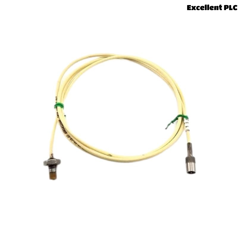
Proximitor Extension Cable Application
- Connects proximity probes to proximitor sensors
- Transfers shaft displacement and vibration signals
- Supports long-distance signal transmission
- Interfaces with PLC Controller and monitoring modules
Preparation Before Extension Cable Installation
- Inspect cable sheath for transport damage
- Verify connector cleanliness before installation
- Check cable impedance compatibility with monitoring systems
- Confirm cable length matches machinery layout requirements
Extension Cable Routing and Mechanical Protection
- Separate signal cable from inverter and motor wiring
- Use grounded cable trays whenever possible
- Avoid sharp bending near connector areas
- Secure cable to prevent vibration-induced movement
  // Signal Routing Validation
  IF Cable_Parallel_To_Power_Line = TRUE THEN
      EMI_Interference_Risk = HIGH;
  ELSE
      Signal_Quality = STABLE;
  END_IF;
Connector Assembly and Shielding Verification
- Clean connectors before coupling
- Ensure connectors are fully tightened
- Verify shielding continuity after installation
- Protect connector areas from oil and moisture ingress
System Configuration and Signal Matching
- Verify extension cable compatibility with proximitor systems
- Check monitoring rack scaling parameters
- Validate alarm threshold configuration
- Confirm grounding integrity across the monitoring network
Startup Validation and Commissioning Process
- Observe waveform stability during startup
- Monitor gap voltage under load conditions
- Check signal noise at rated machine speed
- Verify stable displacement trend recording
Real Industrial Installation Case
During commissioning of a centrifugal compressor monitoring system, intermittent vibration alarms appeared during acceleration:
- Signal spikes increased by approximately 32%
- Gap voltage fluctuated during startup
We observed that the extension cable was routed close to a variable frequency drive power cable for more than 10 meters.
After corrective actions:
- Re-routed extension cable through isolated grounded trays
- Improved shielding continuity at connector junctions
Result:
- Stable vibration waveform restored
- False displacement alarms eliminated
Installation FAQ
Why is cable routing critical for proximitor extension cables?
Poor routing near high-power electrical systems can introduce EMI interference into vibration signals.
Can connector contamination affect shaft monitoring accuracy?
Yes. Oxidized or contaminated connectors can increase resistance and distort signal transmission.
Should extension cables be mechanically supported?
Yes. Unsupported cables may transfer vibration stress into connector assemblies and monitoring systems.
Final Engineering Summary
The Bently Nevada 21747-040-01 Installation Guide demonstrates that reliable vibration monitoring depends on proper extension cable routing, stable shielding continuity, and accurate System Configuration.