

Table of Contents
- 22810-00-04-10-02 Installation Overview
- 7200 Series 8 mm Standard Mount Probe Application
- Mechanical Inspection Before Probe Installation
- Probe Mounting and Gap Adjustment Strategy
- Signal Wiring and Shielding Configuration
- Startup Commissioning and Dynamic Validation
- Probe Signal Optimization Techniques
- Real Compressor Installation Experience
- Installation FAQ
- Final Engineering Summary
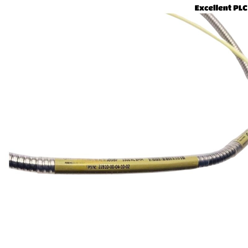
22810-00-04-10-02 Installation Overview
Bently Nevada 22810-00-04-10-02 7200 Series 8 mm standard mount probe installation quality directly affects shaft vibration monitoring stability and machinery protection accuracy. In centrifugal compressors and steam turbines, improper probe alignment and incorrect gap adjustment are common causes of unstable displacement signals.
This Installation Guide explains practical Setup methods for probe mounting, target alignment, signal wiring, and vibration monitoring Commissioning.
7200 Series 8 mm Standard Mount Probe Application
- Measures shaft displacement and radial vibration
- Supports continuous machinery protection monitoring
- Interfaces with PLC Controller and vibration monitoring systems
- Used in compressors, turbines, and industrial rotating equipment
Mechanical Inspection Before Probe Installation
- Inspect mounting thread condition before installation
- Verify shaft target surface cleanliness
- Check bracket rigidity and thermal stability
- Ensure sufficient clearance around the probe tip
Probe Mounting and Gap Adjustment Strategy
Standard mount probes require stable mechanical positioning to maintain accurate shaft displacement measurements.
- Align probe perpendicular to shaft surface
- Adjust probe gap to recommended voltage range
- Avoid excessive tightening torque on probe threads
- Secure extension cable to minimize vibration transfer
  // Probe Gap Verification
  IF Gap_Voltage < -8V OR Gap_Voltage > -10V THEN
      Re_Adjust_Probe_Position();
  ELSE
      Continue_Commissioning();
  END_IF;
Signal Wiring and Shielding Configuration
- Separate probe cables from motor power wiring
- Maintain shielding continuity across connectors
- Use grounded trays for long cable runs
- Verify monitoring rack input scaling parameters
Startup Commissioning and Dynamic Validation
- Observe displacement waveform during startup
- Monitor signal stability at rated speed
- Check thermal influence on gap voltage
- Verify alarm and shutdown response logic
Probe Signal Optimization Techniques
- Reduce cable vibration near probe connectors
- Improve grounding continuity to reduce noise
- Monitor waveform harmonics during operation
- Record baseline vibration values after commissioning
Real Compressor Installation Experience
During commissioning of a centrifugal compressor protection system, unstable shaft vibration readings appeared during acceleration:
- Gap voltage fluctuated from -9.2V to -6.1V
- Waveform spikes increased during speed changes
We observed that the mounting bracket rigidity was insufficient near the probe location.
After corrective actions:
- Reinforced the mounting structure
- Adjusted probe alignment and cable support
Result:
- Stable shaft monitoring restored
- False vibration alarms eliminated
Installation FAQ
Why is probe gap voltage important?
Incorrect gap voltage may cause unstable displacement readings and inaccurate vibration monitoring.
Can bracket vibration affect probe signals?
Yes. Weak mounting structures may introduce mechanical noise into shaft displacement measurements.
Should probe cables be isolated from power wiring?
Yes. Proper cable separation reduces EMI interference and improves signal stability.
Final Engineering Summary
The Bently Nevada 22810-00-04-10-02 Installation Guide demonstrates that reliable vibration monitoring depends on stable probe mounting, accurate gap Setup, proper shielding continuity, and optimized System Configuration.