

Yokogawa ADV551 Digital Output Module installation problems are most often caused by incorrect field wiring, unsuitable output load connections, or incomplete System Configuration instead of hardware failure. Following a structured Installation Guide helps engineers complete Setup and Commissioning safely while ensuring reliable digital output control for valves, relays, motor starters, and other field devices.
Contents
- 1. Yokogawa ADV551 Digital Output Module Overview
- 2. Typical Applications of the ADV551 Digital Output Module
- 3. Installation Planning Before Setup
- 4. Hardware Inspection Before Installation
- 5. Cabinet Environment Requirements
- 6. Power Supply Verification
- 7. ADV551 Module Mounting Procedure
- 8. ADV551 Wiring Installation Guide
- 9. Digital Output Load Design
- 10. Grounding and Cable Shielding
- 11. ADV551 System Configuration
- 12. Commissioning Procedure
- 13. Functional Verification
- 14. Preventive Maintenance
- 15. Real Commissioning Case
- 16. FAQ
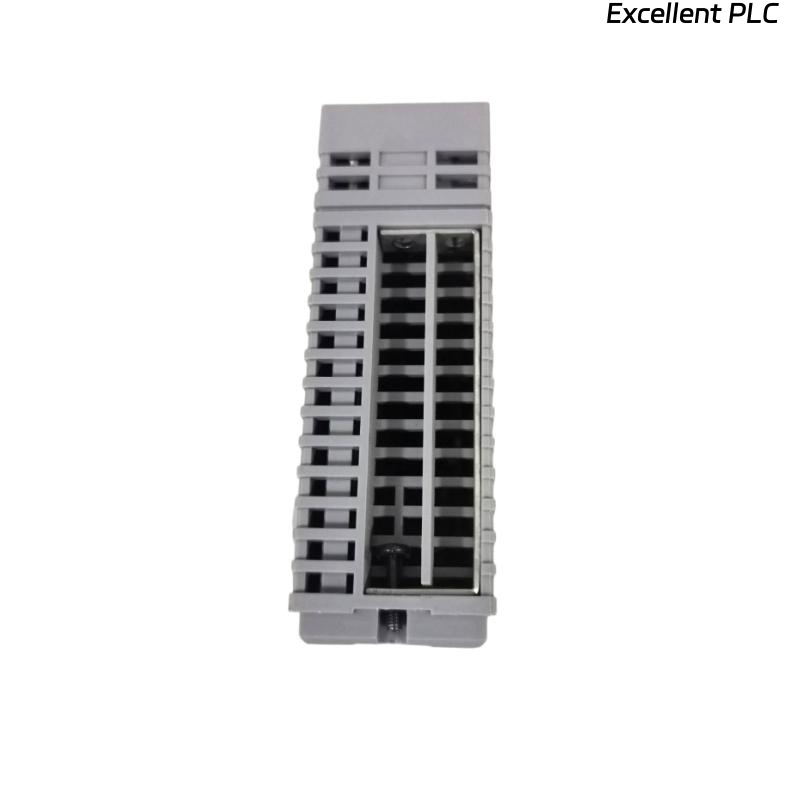
Yokogawa ADV551 Digital Output Module Overview
The Yokogawa ADV551 Digital Output Module is designed to transmit digital control signals from the controller to field equipment. Typical controlled devices include solenoid valves, relay coils, motor starters, annunciators, alarm lamps, and shutdown circuits. Stable output performance depends on proper installation, correct wiring practices, and accurate system configuration.
Typical Applications of the ADV551 Digital Output Module
- Motor start and stop control
- Pump control logic
- Valve open and close commands
- Alarm output circuits
- Emergency shutdown systems
- Remote relay control
Installation Planning Before Setup
Installation begins long before the module is inserted into the cabinet. Experienced commissioning engineers first verify all engineering documentation, including I/O allocation drawings, terminal schedules, control narratives, and loop diagrams.
- Review cabinet layout
- Verify module location
- Prepare output channel list
- Confirm power availability
- Prepare commissioning checklist
Hardware Inspection Before Installation
- Check model number
- Inspect module housing
- Verify connector condition
- Inspect terminal blocks
- Check mechanical damage
Cabinet Environment Requirements
- Maintain clean cabinet ventilation
- Avoid excessive humidity
- Keep away from vibration sources
- Separate power and signal wiring
- Provide adequate maintenance space
Power Supply Verification
Before energizing the system, verify that the external power supply matches the output device requirements. Output problems frequently originate from unstable field power rather than the controller.
- Measure DC voltage
- Verify polarity
- Inspect protection fuses
- Check output common terminals
- Confirm voltage stability
ADV551 Module Mounting Procedure
- Switch off cabinet power.
- Insert the ADV551 module into the assigned slot.
- Lock the retaining mechanism.
- Connect terminal assemblies.
- Inspect connector engagement.
- Restore system power.
ADV551 Wiring Installation Guide
The Installation Guide recommends separating output wiring from high-voltage power cables to reduce electromagnetic interference. Proper cable identification also simplifies future Troubleshooting.
- Use correctly sized conductors
- Label every output channel
- Verify terminal numbering
- Inspect screw torque
- Perform continuity testing
Digital Output Load Design
Every output channel should operate within its rated electrical capacity. Oversized loads may cause voltage drops, output instability, or shortened relay life.
- Check relay coil current
- Verify solenoid ratings
- Review inductive load protection
- Inspect suppression devices
- Avoid output overload
Grounding and Cable Shielding
- Use single-point grounding
- Terminate shields correctly
- Avoid ground loops
- Inspect cabinet bonding
- Verify earth continuity
ADV551 System Configuration
SCAN MODULE
VERIFY NODE STATUS
ASSIGN OUTPUT CHANNELS
MAP CONTROL TAGS
DOWNLOAD DATABASE
SAVE CONFIGURATION
ENABLE OUTPUTS
Commissioning Procedure
Commissioning should always include live field verification. Simulated output testing cannot identify incorrectly wired valves or relay circuits.
- Issue manual output commands
- Observe field response
- Confirm operator display
- Verify alarm operation
- Record commissioning results
Functional Verification
- Measure output voltage
- Verify relay activation
- Check valve movement
- Confirm interlock execution
- Monitor controller diagnostics
Preventive Maintenance
- Inspect terminals annually
- Test critical outputs regularly
- Review diagnostic records
- Verify grounding condition
- Maintain project backups
Real Commissioning Case
During commissioning of a pharmaceutical production line, eight output channels connected to an ADV551 Digital Output Module failed to energize pneumatic valves.
Instead of replacing the module immediately, engineers measured the output voltage and found stable 24.1 VDC at every channel. This indicated that the controller was functioning correctly.
Further investigation showed that the external valve power supply shared an incorrectly wired return conductor after recent cabinet modifications.
After correcting the wiring:
- All pneumatic valves responded normally.
- Output response time decreased from approximately 650 ms to less than 120 ms.
- Commissioning finished without replacing the Digital Output Module.
This project demonstrated that field wiring remains the primary source of commissioning delays for digital output systems.
ADV551 Installation Guide FAQ
What devices can the ADV551 Digital Output Module control?
The module is commonly used for relay outputs, motor starters, solenoid valves, alarm circuits, indicator lamps, and process shutdown devices.
Why is output load verification important?
Incorrect load sizing may result in unstable outputs, voltage drops, or premature failure of connected field devices.
Should commissioning rely only on software simulation?
No. Live field testing is recommended because it confirms that controller commands produce the expected physical equipment response.
Summary: Successful ADV551 Installation, Setup, and Commissioning depend on accurate wiring, suitable output load design, reliable grounding, and complete System Configuration before plant startup.