

The Yokogawa ADV557 Digital Output Module is designed for reliable discrete output control in industrial Distributed Control Systems (DCS). Most installation problems originate from incorrect field wiring, unsuitable load connections, or improper System Configuration rather than module hardware defects. Following this Installation Guide helps engineers complete Setup and Commissioning efficiently while improving long-term system reliability.
Contents
- 1. Yokogawa ADV557 Digital Output Module Overview
- 2. Main Features and Advantages
- 3. Typical Industrial Applications
- 4. Installation Planning
- 5. Hardware Inspection Before Installation
- 6. Environmental Requirements
- 7. Power Supply Verification
- 8. Module Mounting Procedure
- 9. ADV557 Wiring Installation Guide
- 10. Grounding and Shielding
- 11. System Configuration
- 12. Commissioning Procedure
- 13. Functional Verification
- 14. Preventive Maintenance
- 15. Real Commissioning Case
- 16. FAQ
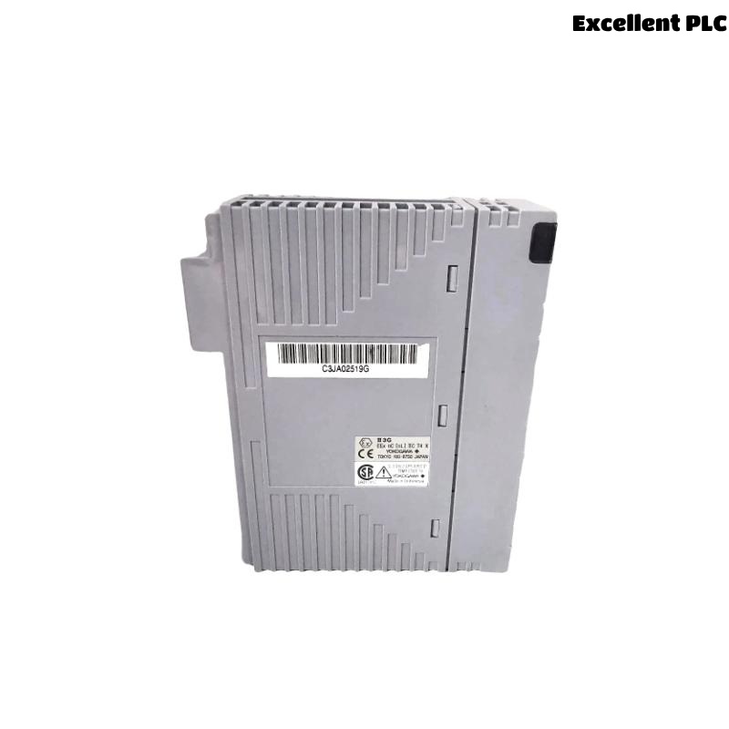
Yokogawa ADV557 Digital Output Module Overview
The ADV557 Digital Output Module provides 32 isolated transistor output channels for industrial automation systems. It is widely applied in Yokogawa CENTUM VP and related DCS platforms to control relays, solenoid valves, contactors, indicator lamps, and other field devices using 24 VDC outputs. Proper installation ensures stable switching performance and minimizes unexpected production interruptions.
Main Features and Advantages
- 32 isolated digital output channels
- 24 VDC transistor outputs
- Current-sink output architecture
- High electrical isolation
- Fast switching response
- Suitable for redundant DCS systems
Typical Industrial Applications
- Valve control
- Motor starter control
- Relay switching
- Emergency shutdown systems
- Alarm annunciation
- Process automation
Installation Planning
Installation begins with engineering preparation rather than physical wiring. Confirm the latest project documentation before connecting field devices.
- Verify I/O allocation
- Review wiring drawings
- Confirm terminal schedules
- Prepare commissioning checklist
- Verify cabinet layout
Hardware Inspection Before Installation
- Confirm module identification
- Inspect connectors
- Check housing integrity
- Inspect terminal assemblies
- Verify locking mechanism
Environmental Requirements
- Maintain clean cabinet ventilation
- Avoid excessive humidity
- Reduce vibration exposure
- Separate signal and power wiring
- Maintain proper grounding
Power Supply Verification
- Measure 24 VDC supply voltage
- Verify polarity
- Inspect protective fuses
- Check voltage stability
- Confirm common return wiring
Module Mounting Procedure
- Disconnect cabinet power.
- Insert the ADV557 into the designated slot.
- Lock the retaining mechanism.
- Connect the terminal block.
- Inspect mechanical engagement.
- Restore cabinet power.
ADV557 Wiring Installation Guide
Proper cable routing and terminal identification reduce future maintenance time and simplify Troubleshooting.
- Separate output and AC power cables
- Label every output channel
- Verify terminal numbering
- Inspect cable insulation
- Perform continuity testing
Grounding and Shielding
- Use single-point grounding
- Terminate cable shields correctly
- Avoid ground loops
- Verify cabinet bonding
- Inspect earth continuity
System Configuration
SCAN MODULE
VERIFY NODE STATUS
ASSIGN OUTPUT CHANNELS
MAP CONTROL TAGS
DOWNLOAD CONFIGURATION
SAVE PROJECT
ENABLE OUTPUTS
Commissioning Procedure
- Execute manual output commands
- Observe relay operation
- Verify valve movement
- Confirm operator graphics
- Record commissioning results
Functional Verification
- Measure output voltage
- Verify response time
- Inspect output LEDs
- Confirm field device operation
- Review controller diagnostics
Preventive Maintenance
- Inspect terminals every six months
- Verify grounding annually
- Review controller diagnostics
- Check output wiring
- Maintain project backups
Real Commissioning Case
During commissioning of a refinery process unit, several relay outputs controlled by an ADV557 Digital Output Module failed to energize despite successful controller startup.
Electrical measurements showed normal 24 VDC output directly at the module. However, the relay coils received less than 12 VDC during operation.
Inspection of the marshalling cabinet identified a loose pressure-clamp terminal that created excessive resistance in the common return path.
After correcting the terminal connection:
- All relay outputs responded immediately.
- Output voltage remained stable under full load.
- No module replacement was required.
- The system completed commissioning without further output alarms.
ADV557 Installation Guide FAQ
What field devices can the ADV557 Digital Output Module control?
The module is commonly used to control relays, solenoid valves, contactors, motor starters, alarm lamps, and other 24 VDC field devices.
Why should output wiring be separated from power cables?
Proper cable separation minimizes electromagnetic interference and improves long-term output stability.
Is software simulation sufficient during commissioning?
No. Live functional testing confirms that controller commands produce the expected response from actual field equipment.
Summary: Successful installation of the Yokogawa ADV557 Digital Output Module depends on careful engineering preparation, correct wiring, stable power supplies, reliable grounding, and comprehensive commissioning tests to ensure dependable industrial control performance.