

Table of Contents
- 21504-000-008-05-02 Installation Overview
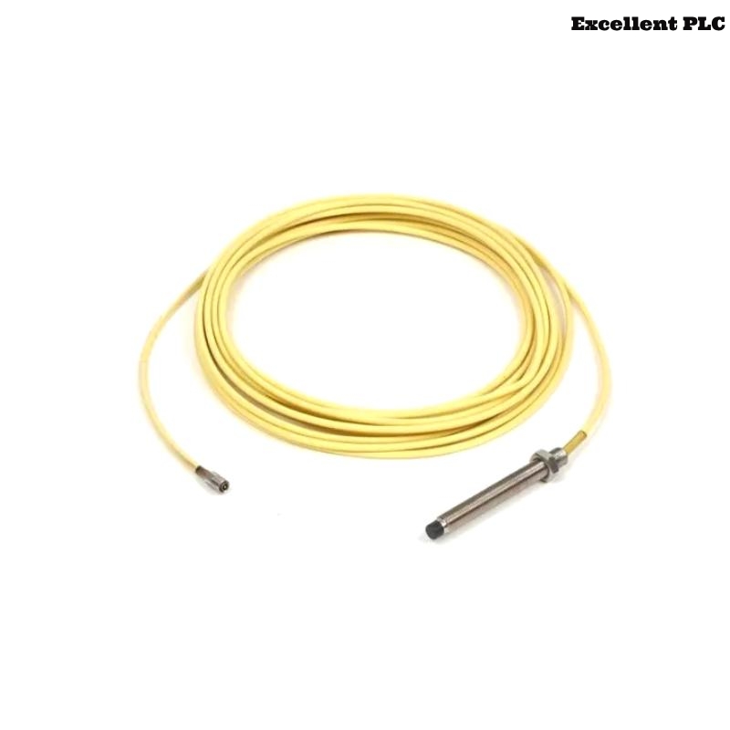
- 7200 8 mm Standard Mount Probe Application
- Installation Planning and Mechanical Preparation
- Probe Alignment and Standard Mounting Method
- Gap Calibration and Signal Verification
- Monitoring System Integration and Setup
- Commissioning Strategy and Dynamic Validation
- Real Field Commissioning Case
- Installation FAQ
- Final Engineering Summary
21504-000-008-05-02 Installation Overview
Bently Nevada 21504-000-008-05-02 7200 8 mm standard mount probe installation directly impacts shaft vibration monitoring accuracy and machinery protection reliability. Improper mounting geometry or incorrect gap adjustment commonly causes unstable displacement readings during machine startup.
This Installation Guide explains practical Setup methods for probe alignment, signal calibration, System Configuration, and vibration monitoring Commissioning.
7200 8 mm Standard Mount Probe Application
- Measures radial shaft vibration and position
- Supports turbine, compressor, and motor protection systems
- Provides continuous displacement signals to monitoring racks
- Interfaces with PLC Controller and vibration analysis modules
Installation Planning and Mechanical Preparation
- Inspect mounting threads and bracket condition
- Verify shaft target surface cleanliness
- Check available clearance around probe body
- Confirm compatible extension cable and proximitor model
Probe Alignment and Standard Mounting Method
- Install probe perpendicular to shaft surface
- Maintain stable mounting rigidity
- Avoid side loading on probe threads
- Secure cable routing against vibration movement
  // Probe Alignment Verification
  IF Probe_Angle != 90deg THEN
      Signal_Accuracy = LOW;
  ELSE
      Continue_Gap_Calibration();
  END_IF;
Gap Calibration and Signal Verification
- Adjust probe until static gap voltage reaches -8V to -10V
- Verify stable voltage during shaft rotation
- Check waveform symmetry during startup
- Store baseline vibration values for future Troubleshooting
Monitoring System Integration and Setup
- Use shielded signal cable routing
- Separate low-level signal wiring from power cables
- Ensure proper grounding continuity
- Verify monitoring channel scaling and alarm settings
Commissioning Strategy and Dynamic Validation
- Observe displacement waveform during startup
- Monitor gap voltage stability under load
- Compare vibration readings across channels
- Validate machinery protection alarms
Real Field Commissioning Case
During commissioning of a centrifugal compressor, abnormal shaft displacement alarms appeared after load increase:
- Gap voltage drifted from -9.3V to -6.7V
- Vibration waveform became unstable
We observed that the probe bracket loosened slightly due to thermal expansion.
After corrective actions:
- Reinforced bracket rigidity
- Reset probe gap to -9V
Result:
- Stable vibration trend restored
- False shutdown alarms eliminated
Installation FAQ
What gap voltage should be used for the 7200 8 mm probe?
Most applications operate normally between -8V and -10V DC.
Why is probe alignment important?
Incorrect alignment reduces signal linearity and affects displacement accuracy.
Can cable routing affect vibration measurements?
Yes. EMI interference from nearby power wiring can distort low-level probe signals.
Final Engineering Summary
The Bently Nevada 21504-000-008-05-02 Installation Guide highlights that correct probe alignment, rigid mounting, and proper System Configuration are essential for reliable machinery vibration monitoring and protection.