

Table of Contents
- 21505-000-012-05-02 Installation Overview
- 7200 8 mm Armored Probe Function in Machinery Protection
- Installation Environment and Site Assessment
- Armored Probe Mounting and Mechanical Protection
- Probe Gap Setup and Calibration Process
- Armored Cable Routing and System Configuration
- Commissioning and Dynamic Signal Verification
- Real Industrial Installation Case
- Installation FAQ
- Final Engineering Summary
21505-000-012-05-02 Installation Overview
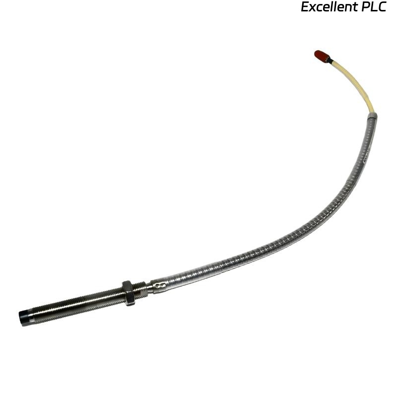
Bently Nevada 21505-000-012-05-02 7200 8 mm armored standard mount probe installation quality directly affects shaft vibration monitoring stability and long-term machinery protection reliability. In harsh industrial environments, armored cable routing and mounting rigidity are often more critical than the probe electronics themselves.
This Installation Guide explains practical field Setup methods for armored probe positioning, signal calibration, cable protection, and vibration monitoring Commissioning.
7200 8 mm Armored Probe Function in Machinery Protection
- Measures shaft vibration and displacement without physical contact
- Provides durable signal transmission in harsh environments
- Supports turbines, compressors, and heavy rotating equipment
- Interfaces with PLC Controller and vibration monitoring systems
Installation Environment and Site Assessment
- Inspect vibration exposure near cable routing path
- Check ambient temperature around probe mounting area
- Verify clearance for armored cable bending radius
- Ensure probe location allows future maintenance access
Armored Probe Mounting and Mechanical Protection
- Install probe perpendicular to shaft target surface
- Secure armored cable to prevent vibration fatigue
- Avoid excessive bending near armored cable entry
- Use rigid mounting brackets to minimize movement
  // Installation Validation Logic
  IF Cable_Bend_Radius < Minimum_Limit THEN
      Risk_Of_Cable_Damage = TRUE;
  ELSE
      Continue_Commissioning();
  END_IF;
Probe Gap Setup and Calibration Process
- Adjust probe until output reaches operating voltage range
- Typical gap voltage target: -8V to -10V
- Monitor voltage stability during shaft rotation
- Record baseline readings for future Troubleshooting
Armored Cable Routing and System Configuration
- Separate armored signal cable from motor power wiring
- Maintain grounding continuity across the monitoring system
- Secure cable supports to avoid vibration movement
- Verify channel scaling and alarm settings
Commissioning and Dynamic Signal Verification
- Observe vibration waveform during startup
- Check displacement trend stability under load
- Inspect signal noise level at operating speed
- Validate alarm thresholds and shutdown logic
Real Industrial Installation Case
During commissioning of a gas compressor, unstable displacement alarms occurred after several hours of operation:
- Gap voltage drifted from -9V to -6.8V
- Signal spikes increased during high-load operation
We observed that the armored cable was unsupported near the probe housing and experienced continuous vibration stress.
After corrective actions:
- Added vibration-resistant cable clamps
- Recalibrated probe gap to -9.1V
Result:
- Stable displacement monitoring restored
- Signal noise reduced significantly
Installation FAQ
Why is armored cable support important?
Unsupported armored cables can transfer vibration stress directly to the probe connection.
What is the recommended operating gap voltage?
Typical systems operate reliably between -8V and -10V DC.
Can tight cable bending damage the armored probe assembly?
Yes. Excessive bending can weaken cable shielding and internal conductors.
Final Engineering Summary
The Bently Nevada 21505-000-012-05-02 Installation Guide demonstrates that correct armored cable routing, stable probe alignment, and accurate gap Setup are essential for reliable vibration monitoring and machinery protection.