

Table of Contents
- 21505-00-60-10-02 Installation Overview
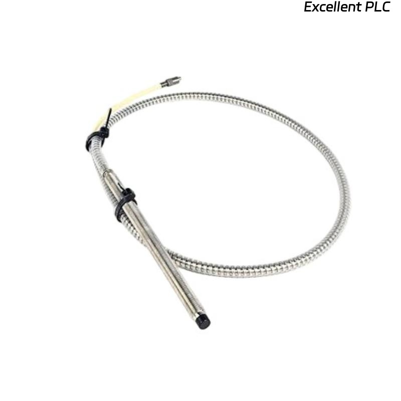
- 7200 8 mm Armored Probe Application in Turbine Monitoring
- Long-Distance Installation Strategy
- Probe Mounting and Mechanical Stability
- Electrical Setup and Gap Voltage Adjustment
- Armored Cable Routing and System Configuration
- Startup Commissioning and Dynamic Validation
- Real Industrial Installation Case
- Installation FAQ
- Final Engineering Summary
21505-00-60-10-02 Installation Overview
Bently Nevada 21505-00-60-10-02 7200 8 mm armored standard mount probe installations require stable cable routing and vibration-resistant mounting to maintain accurate shaft displacement monitoring. In long-distance installations, armored cable vibration and grounding quality often determine overall monitoring reliability.
This Installation Guide explains practical methods for probe Setup, gap calibration, armored cable protection, and machinery protection Commissioning.
7200 8 mm Armored Probe Application in Turbine Monitoring
- Measures radial shaft vibration and displacement
- Supports continuous machinery protection systems
- Operates in harsh industrial environments
- Interfaces with PLC Controller and vibration monitoring racks
Long-Distance Installation Strategy
- Inspect cable tray routing before installation
- Maintain separation from inverter power cables
- Verify support points for long armored cable sections
- Ensure access for future maintenance and Troubleshooting
Probe Mounting and Mechanical Stability
- Install probe perpendicular to shaft surface
- Use rigid mounting hardware to reduce vibration transfer
- Support armored cable close to the probe housing
- Avoid excessive cable bending and twisting
  // Mechanical Stability Check
  IF Probe_Bracket_Movement = TRUE THEN
      Signal_Stability = LOW;
  ELSE
      Continue_Gap_Setup();
  END_IF;
Electrical Setup and Gap Voltage Adjustment
- Adjust probe gap until voltage stabilizes between -8V and -10V
- Observe waveform quality during slow shaft rotation
- Verify stable signal output during startup
- Record baseline values for future Fault Diagnosis
Armored Cable Routing and System Configuration
- Use grounded cable trays for long cable routing
- Separate signal and motor wiring paths
- Verify shielding continuity across all junctions
- Check alarm and shutdown parameter settings
Startup Commissioning and Dynamic Validation
- Monitor displacement trends during acceleration
- Observe signal noise at rated speed
- Check thermal influence on probe gap voltage
- Validate machinery protection logic response
Real Industrial Installation Case
During commissioning of a gas turbine monitoring system, unstable displacement readings appeared after reaching operating speed:
- Gap voltage drifted from -9V to -6.3V
- Signal spikes increased during load transitions
We observed that the long armored cable section was unsupported near a vibrating structural frame.
After corrective actions:
- Installed vibration-resistant cable clamps
- Improved grounding continuity
Result:
- Stable displacement monitoring restored
- False shutdown alarms eliminated
Installation FAQ
Why are long armored cable installations sensitive to vibration?
Unsupported cable sections can transfer mechanical movement into the probe assembly.
What is the recommended operating gap voltage?
Typical systems operate reliably between -8V and -10V DC.
Can poor grounding affect vibration signal quality?
Yes. Grounding faults commonly create signal noise and unstable readings.
Final Engineering Summary
The Bently Nevada 21505-00-60-10-02 Installation Guide demonstrates that reliable vibration monitoring depends on correct armored cable routing, stable mechanical installation, and accurate System Configuration.