

Table of Contents
- 21505-00-72-10-02 Installation Overview
- 7200 8 mm Armored Probe Function in Machinery Monitoring
- Installation Environment and Risk Assessment
- Probe Mounting and Armored Cable Protection
- Gap Setup and Electrical Calibration
- System Configuration and Long Cable Routing
- Startup Validation and Commissioning Procedure
- Real Turbine Installation Experience
- Installation FAQ
- Final Engineering Summary
21505-00-72-10-02 Installation Overview
Bently Nevada 21505-00-72-10-02 7200 8 mm armored standard mount probe installations require stable mechanical mounting and controlled armored cable routing to ensure accurate shaft vibration monitoring. In extended cable applications, vibration transfer and grounding quality are often more important than the probe electronics themselves.
This Installation Guide explains practical methods for armored probe Setup, signal calibration, cable routing, and machinery protection Commissioning.
7200 8 mm Armored Probe Function in Machinery Monitoring
- Measures radial shaft vibration and displacement
- Supports continuous turbine and compressor protection
- Provides reliable non-contact monitoring
- Interfaces with PLC Controller and vibration monitoring modules
Installation Environment and Risk Assessment
- Inspect armored cable routing path for vibration exposure
- Verify separation from inverter and motor power cables
- Check ambient temperature near mounting location
- Ensure maintenance access around probe housing
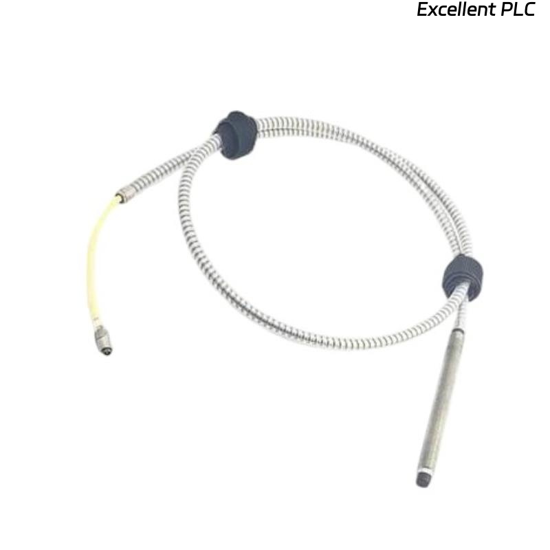
Probe Mounting and Armored Cable Protection
- Install probe perpendicular to shaft surface
- Secure armored cable close to the probe body
- Prevent cable twisting during installation
- Use rigid brackets to minimize vibration transfer
  // Installation Stability Logic
  IF Cable_Movement = HIGH THEN
      Signal_Quality = UNSTABLE;
  ELSE
      Continue_Commissioning();
  END_IF;
Gap Setup and Electrical Calibration
- Adjust probe until voltage stabilizes between -8V and -10V
- Verify waveform quality during shaft rotation
- Check signal linearity under varying speed
- Store baseline readings for future Troubleshooting
System Configuration and Long Cable Routing
- Route signal cable separately from power systems
- Use grounded trays for extended armored cable runs
- Verify shielding continuity across all connectors
- Check monitoring rack scaling and alarm settings
Startup Validation and Commissioning Procedure
- Observe displacement trends during acceleration
- Monitor signal noise at operating speed
- Check thermal influence on gap voltage
- Validate shutdown and protection logic
Real Turbine Installation Experience
During commissioning of a steam turbine monitoring system, intermittent displacement alarms occurred during speed ramp-up:
- Gap voltage fluctuated from -9V to -6.2V
- Signal spikes appeared near rated speed
We observed that a long unsupported armored cable section vibrated continuously against the turbine frame.
After corrective actions:
- Installed isolated cable support brackets
- Improved shielding and grounding continuity
Result:
- Stable vibration monitoring restored
- False alarms eliminated
Installation FAQ
Why is armored cable support critical in long-distance installations?
Unsupported cable sections can transfer vibration stress into the probe assembly and destabilize the signal.
What operating gap voltage is recommended?
Most systems operate reliably within the -8V to -10V DC range.
Can poor cable routing affect machinery protection reliability?
Yes. EMI interference and vibration-induced cable movement can create unstable readings.
Final Engineering Summary
The Bently Nevada 21505-00-72-10-02 Installation Guide demonstrates that stable probe mounting, accurate gap Setup, and proper armored cable routing are essential for reliable machinery vibration monitoring.