

Table of Contents
- 21505-04-12-90-02 Installation Overview
- 7200 8 mm Armored Probe Role in Shaft Monitoring
- Installation Planning and Risk Prevention
- Mechanical Installation and Probe Stability
- Electrical Setup and Gap Voltage Calibration
- Long Cable Routing and System Configuration
- Commissioning Procedure and Signal Validation
- Real Industrial Installation Experience
- Installation FAQ
- Final Engineering Summary
21505-04-12-90-02 Installation Overview
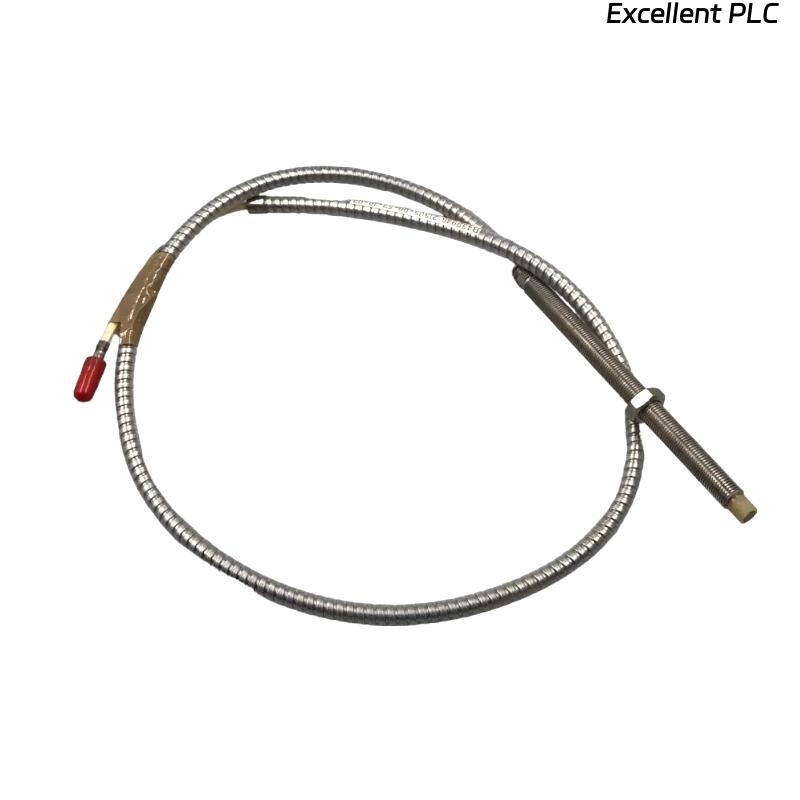
Bently Nevada 21505-04-12-90-02 7200 8 mm armored standard mount probe installation accuracy directly affects shaft displacement monitoring reliability and machinery protection performance. In extended cable installations, improper grounding and armored cable vibration are common causes of unstable signals during startup and load transitions.
This Installation Guide explains practical Setup methods for armored probe alignment, cable management, gap adjustment, and vibration monitoring Commissioning.
7200 8 mm Armored Probe Role in Shaft Monitoring
- Measures shaft vibration and radial displacement
- Supports turbine and compressor protection systems
- Provides non-contact vibration monitoring
- Interfaces with PLC Controller and machinery monitoring racks
Installation Planning and Risk Prevention
- Inspect armored cable path before installation
- Verify separation from inverter and motor cables
- Check vibration exposure near mounting location
- Ensure sufficient maintenance clearance around the probe assembly
Mechanical Installation and Probe Stability
- Install probe perpendicular to shaft target surface
- Use rigid mounting brackets to reduce mechanical movement
- Support armored cable close to the probe housing
- Avoid excessive cable bending and twisting forces
  // Mechanical Stability Validation
  IF Probe_Bracket_Vibration > Threshold THEN
      Signal_Quality = UNSTABLE;
  ELSE
      Continue_Gap_Calibration();
  END_IF;
Electrical Setup and Gap Voltage Calibration
- Adjust probe until voltage stabilizes between -8V and -10V
- Verify waveform quality during shaft rotation
- Check signal linearity at operating speed
- Record baseline values for future Fault Diagnosis
Long Cable Routing and System Configuration
- Route armored signal cable separately from power wiring
- Use grounded trays for long-distance cable runs
- Verify shielding continuity across all connections
- Check monitoring rack scaling and alarm parameters
Commissioning Procedure and Signal Validation
- Monitor displacement trends during startup
- Observe signal noise at rated speed
- Check thermal influence on gap voltage stability
- Validate machinery protection logic response
Real Industrial Installation Experience
During commissioning of a refinery turbine system, repeated displacement alarms occurred during speed increase:
- Gap voltage fluctuated from -9.2V to -6.3V
- Signal spikes appeared during load changes
We observed that the armored cable lacked proper support near a vibrating support beam.
After corrective actions:
- Installed vibration-resistant cable clamps
- Improved cable grounding continuity
Result:
- Stable shaft monitoring restored
- False shutdown alarms eliminated
Installation FAQ
Why are armored cable supports important?
Unsupported cables can transfer vibration into the probe assembly and destabilize the signal.
What is the recommended operating voltage range?
Typical systems operate reliably between -8V and -10V DC.
Can long cable routing affect vibration signal quality?
Yes. EMI interference and poor grounding can create unstable readings.
Final Engineering Summary
The Bently Nevada 21505-04-12-90-02 Installation Guide demonstrates that stable probe mounting, proper armored cable routing, and accurate System Configuration are essential for reliable vibration monitoring.