

Table of Contents
- 21508-02-12-05-02 Installation Overview
- 7200 8 mm Reverse Mount Probe Application
- Reverse Mount Installation Planning
- Reverse Probe Mounting and Mechanical Positioning
- Gap Voltage Setup and Signal Calibration
- System Configuration and Signal Wiring
- Commissioning and Dynamic Shaft Validation
- Real Reverse Mount Installation Case
- Installation FAQ
- Final Engineering Summary
21508-02-12-05-02 Installation Overview
Bently Nevada 21508-02-12-05-02 7200 8 mm reverse mount probe installation requires careful mechanical alignment because reverse-mounted probe assemblies are more sensitive to bracket movement and shaft alignment errors than standard mounting designs.
This Installation Guide explains practical Setup methods for reverse mounting, probe positioning, gap voltage calibration, and vibration monitoring Commissioning in turbine and compressor systems.
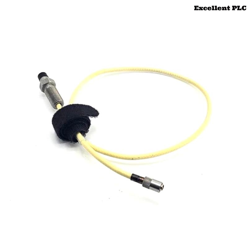
7200 8 mm Reverse Mount Probe Application
- Measures shaft vibration and radial displacement
- Supports reverse-side installation in restricted spaces
- Provides non-contact machinery monitoring
- Interfaces with PLC Controller and monitoring racks
Reverse Mount Installation Planning
- Verify available rear mounting clearance
- Inspect bracket rigidity before installation
- Check target shaft surface condition
- Ensure armored cable routing does not create tension on the probe body
Reverse Probe Mounting and Mechanical Positioning
- Align probe perpendicular to shaft target surface
- Use rigid brackets to minimize resonance
- Support armored cable near reverse mounting location
- Avoid side-loading force during installation
  // Reverse Mount Alignment Logic
  IF Probe_Angle_Error > Allowed_Limit THEN
      Signal_Linearity = FALSE;
  ELSE
      Continue_Gap_Setup();
  END_IF;
Gap Voltage Setup and Signal Calibration
- Adjust probe gap until voltage stabilizes between -8V and -10V
- Verify stable waveform during shaft rotation
- Observe signal behavior during thermal expansion
- Store baseline values for future Troubleshooting
System Configuration and Signal Wiring
- Separate signal cables from motor power wiring
- Maintain shielding continuity across connectors
- Verify monitoring rack channel scaling
- Check alarm and shutdown parameter settings
Commissioning and Dynamic Shaft Validation
- Observe shaft displacement trends during startup
- Monitor waveform stability at rated speed
- Verify stable gap voltage under load changes
- Validate machinery protection logic response
Real Reverse Mount Installation Case
During commissioning of a steam turbine monitoring system, intermittent displacement alarms appeared after startup:
- Gap voltage drifted from -9V to -6.1V
- Waveform distortion increased during thermal expansion
We observed that the reverse-mounted bracket had slight resonance near operating speed.
After corrective actions:
- Reinforced bracket structure
- Adjusted probe alignment and cable support
Result:
- Stable shaft displacement readings restored
- False shutdown alarms eliminated
Installation FAQ
Why are reverse mount probes more sensitive to bracket vibration?
Reverse-mounted assemblies often experience higher structural resonance and alignment stress.
What is the ideal operating gap voltage?
Most systems operate reliably between -8V and -10V DC.
Can reverse mounting affect signal stability?
Yes. Incorrect mounting geometry may reduce signal linearity and increase vibration sensitivity.
Final Engineering Summary
The Bently Nevada 21508-02-12-05-02 Installation Guide demonstrates that accurate reverse probe alignment, stable mounting structures, and proper System Configuration are essential for reliable machinery protection performance.