

Table of Contents
- 21747-040-00 Installation Overview
- Proximitor Probe Extension Cable Function
- Cable Inspection Before Installation
- Extension Cable Routing Strategy
- Connector Installation and Signal Integrity
- System Configuration and Electrical Validation
- Commissioning and Signal Stability Verification
- Real Field Installation Experience
- Installation FAQ
- Final Engineering Summary
21747-040-00 Installation Overview
Bently Nevada 21747-040-00 proximitor probe extension cable installation quality directly affects vibration monitoring accuracy and signal stability. In rotating machinery systems, poor cable routing and connector contamination are common causes of unstable shaft displacement readings and intermittent alarms.
This Installation Guide explains practical Setup methods for extension cable routing, connector installation, shielding protection, and machinery monitoring Commissioning.
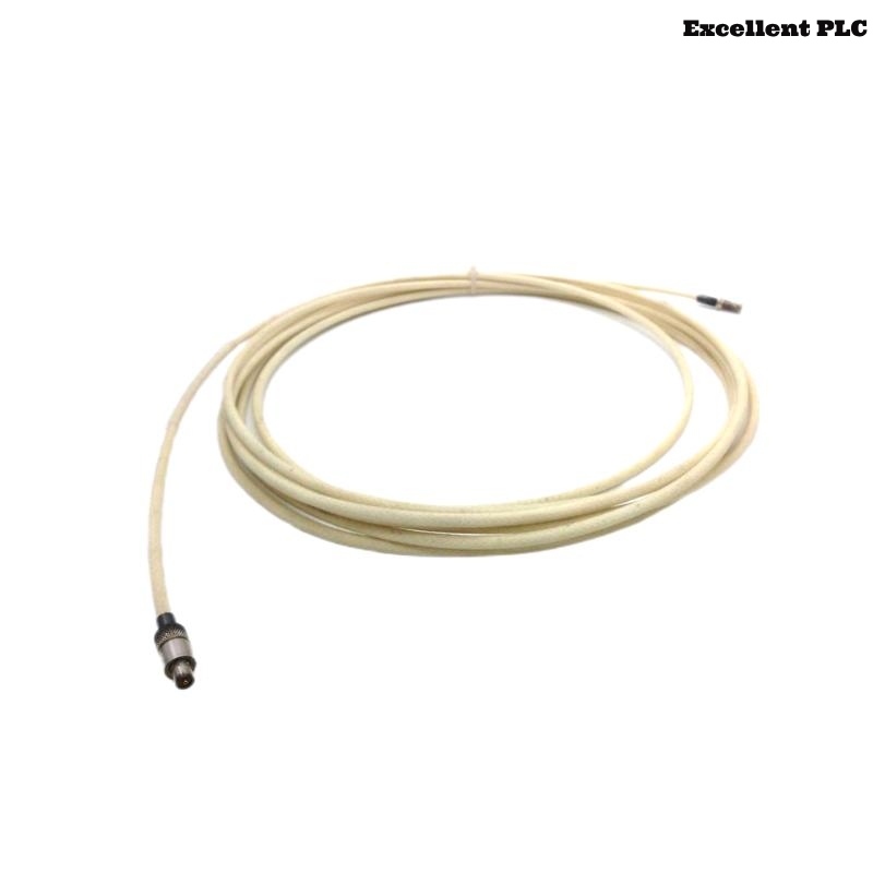
Proximitor Probe Extension Cable Function
- Connects proximity probe to proximitor sensor
- Transfers shaft vibration and displacement signals
- Supports long-distance signal transmission
- Interfaces with PLC Controller and vibration monitoring systems
Cable Inspection Before Installation
- Inspect extension cable sheath for mechanical damage
- Verify connector cleanliness before installation
- Check shielding continuity using a multimeter
- Confirm cable length matches System Configuration requirements
Extension Cable Routing Strategy
- Separate signal cable from high-voltage motor wiring
- Use grounded trays for long-distance routing
- Avoid sharp cable bends near connectors
- Secure cable to prevent vibration-induced movement
  // Cable Routing Validation
  IF Cable_Distance_To_Power_Line < Minimum_Clearance THEN
      EMI_Risk = HIGH;
  ELSE
      Signal_Integrity = NORMAL;
  END_IF;
Connector Installation and Signal Integrity
- Clean connectors before coupling
- Tighten connectors using recommended torque
- Protect connectors from moisture ingress
- Verify continuity after installation
System Configuration and Electrical Validation
- Verify extension cable impedance compatibility
- Check proximitor sensor calibration values
- Confirm monitoring rack scaling parameters
- Validate alarm and shutdown settings
Commissioning and Signal Stability Verification
- Observe vibration waveform during startup
- Monitor signal noise at rated speed
- Verify stable gap voltage under load
- Check long-term signal stability trends
Real Field Installation Experience
During commissioning of a steam turbine monitoring system, intermittent displacement alarms appeared after startup:
- Signal spikes increased by approximately 35%
- Gap voltage fluctuated during speed transitions
We observed that the extension cable was routed parallel to a high-current inverter power line for nearly 15 meters.
After corrective actions:
- Re-routed the extension cable through grounded trays
- Improved shielding continuity at connector joints
Result:
- Signal stability improved significantly
- False vibration alarms disappeared
Installation FAQ
Why should extension cables be separated from motor wiring?
Close routing near power cables may introduce EMI interference into vibration signals.
Can connector contamination affect vibration monitoring?
Yes. Dirty or oxidized connectors can increase signal resistance and create unstable readings.
Should extension cables be mechanically supported?
Yes. Unsupported cable movement may transfer vibration stress into connectors and monitoring systems.
Final Engineering Summary
The Bently Nevada 21747-040-00 Installation Guide demonstrates that stable extension cable routing, proper connector installation, and accurate System Configuration are essential for reliable machinery vibration monitoring.