

Table of Contents
- 21505-022-055-10-02 Installation Overview
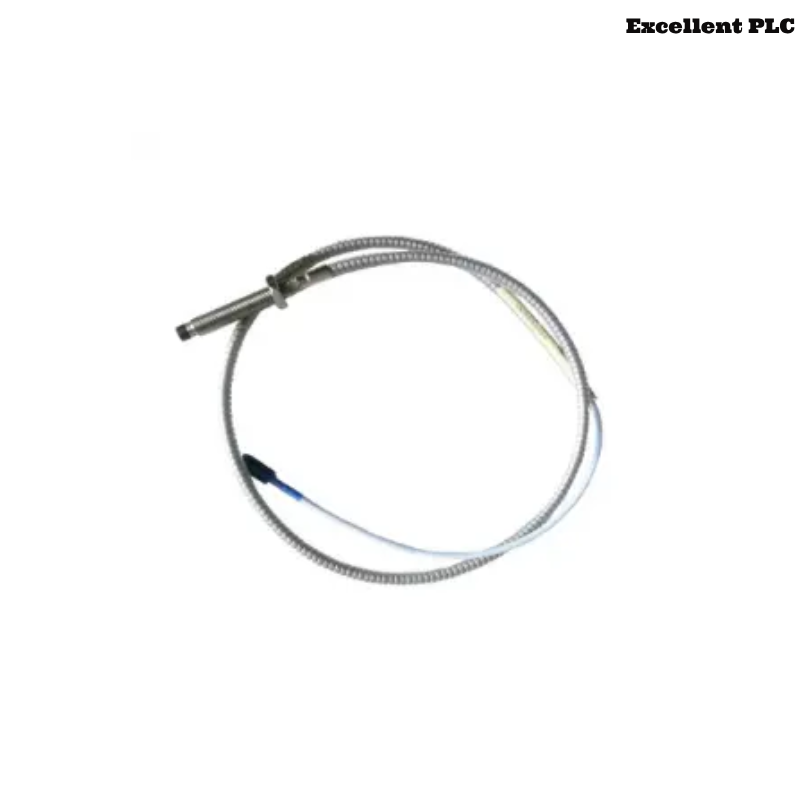
- 7200 8 mm Armored Probe Application in Industrial Machinery
- Site Assessment and Installation Planning
- Probe Mounting and Armored Cable Management
- Gap Calibration and Signal Verification
- Monitoring System Integration and Wiring
- Commissioning Workflow and Dynamic Validation
- Real Field Installation Case
- Installation FAQ
- Final Engineering Summary
21505-022-055-10-02 Installation Overview
Bently Nevada 21505-022-055-10-02 7200 8 mm armored standard mount probe installation quality directly affects shaft displacement monitoring stability and long-term machinery protection performance. In large industrial systems, armored cable vibration and poor routing practices often cause unstable readings during startup and load transitions.
This Installation Guide explains practical Setup methods for probe alignment, armored cable routing, gap adjustment, and vibration monitoring Commissioning.
7200 8 mm Armored Probe Application in Industrial Machinery
- Measures radial shaft vibration and displacement
- Supports turbine and compressor protection systems
- Provides continuous non-contact monitoring
- Interfaces with PLC Controller and vibration monitoring racks
Site Assessment and Installation Planning
- Inspect cable tray routing before installation
- Verify separation from high-current motor wiring
- Check mounting area for excessive structural vibration
- Ensure maintenance access around probe location
Probe Mounting and Armored Cable Management
- Install probe perpendicular to shaft target surface
- Secure armored cable close to the probe body
- Avoid sharp cable bending near connectors
- Use rigid mounting brackets to reduce vibration transfer
  // Installation Validation Logic
  IF Armored_Cable_Movement = HIGH THEN
      Signal_Stability = LOW;
  ELSE
      Continue_Gap_Adjustment();
  END_IF;
Gap Calibration and Signal Verification
- Adjust probe until gap voltage stabilizes between -8V and -10V
- Verify waveform quality during shaft rotation
- Check signal linearity at operating speed
- Record baseline values for future Fault Diagnosis
Monitoring System Integration and Wiring
- Route signal cable separately from inverter power lines
- Maintain shielding continuity across all connections
- Verify grounding quality at the monitoring rack
- Check alarm scaling and System Configuration
Commissioning Workflow and Dynamic Validation
- Observe displacement trends during startup
- Monitor signal noise during load increase
- Check thermal influence on probe gap voltage
- Validate shutdown and protection logic response
Real Field Installation Case
During commissioning of a petrochemical compressor system, intermittent displacement alarms occurred after reaching rated speed:
- Gap voltage fluctuated between -9.1V and -6.4V
- Signal spikes increased during load transitions
We observed that the armored cable was unsupported near a vibrating structural beam.
After corrective actions:
- Installed vibration-resistant cable supports
- Improved shielding and grounding continuity
Result:
- Stable displacement monitoring restored
- False shutdown alarms eliminated
Installation FAQ
Why must armored cables be properly supported?
Unsupported cable sections can transfer mechanical vibration into the probe assembly and affect signal quality.
What operating gap voltage is recommended?
Most applications maintain stable operation between -8V and -10V DC.
Can improper cable routing affect machinery protection systems?
Yes. EMI interference and vibration stress may create unstable displacement readings.
Final Engineering Summary
The Bently Nevada 21505-022-055-10-02 Installation Guide demonstrates that reliable vibration monitoring depends on stable probe mounting, accurate gap Setup, and proper armored cable management.