

Table of Contents
- 21508-02-12-10-02 Installation Overview
- 7200 8 mm Reverse Mount Probe Function
- Pre-Installation Inspection and Engineering Checks
- Reverse Mount Probe Alignment Procedure
- Gap Voltage Setup and Calibration
- Signal Wiring and System Configuration
- Commissioning Validation Under Dynamic Load
- Real Turbine Installation Experience
- Installation FAQ
- Final Engineering Summary
21508-02-12-10-02 Installation Overview
Bently Nevada 21508-02-12-10-02 7200 8 mm reverse mount probe installation quality directly affects shaft vibration monitoring stability and machinery protection reliability. Reverse mounting structures are typically more sensitive to thermal expansion and bracket resonance than standard probe installations.
This Installation Guide explains practical Setup methods for reverse mount probe positioning, gap adjustment, armored cable routing, and machinery protection Commissioning.
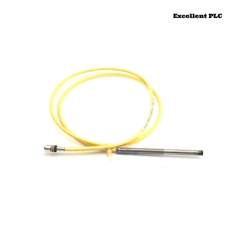
7200 8 mm Reverse Mount Probe Function
- Measures shaft displacement and radial vibration
- Supports reverse-side installation in restricted equipment spaces
- Provides continuous non-contact shaft monitoring
- Interfaces with PLC Controller and vibration monitoring modules
Pre-Installation Inspection and Engineering Checks
- Inspect reverse mounting bracket rigidity
- Verify shaft target surface condition
- Check clearance around the probe housing
- Ensure armored cable routing does not create side-loading force
Reverse Mount Probe Alignment Procedure
- Align probe perpendicular to shaft target surface
- Minimize bracket vibration near operating speed
- Secure armored cable near the probe body
- Avoid excessive tightening force on reverse-mounted assemblies
  // Reverse Mount Alignment Check
  IF Probe_Angle_Error > Allowed_Range THEN
      Signal_Stability = LOW;
  ELSE
      Continue_Gap_Calibration();
  END_IF;
Gap Voltage Setup and Calibration
- Adjust probe gap until voltage stabilizes between -8V and -10V
- Verify waveform quality during shaft rotation
- Observe signal response during thermal growth
- Record baseline operating values for future Troubleshooting
Signal Wiring and System Configuration
- Separate signal cable from motor power wiring
- Maintain shielding continuity across all junctions
- Verify monitoring rack scaling and alarm configuration
- Check grounding integrity before startup
Commissioning Validation Under Dynamic Load
- Observe shaft displacement trends during startup
- Monitor waveform stability at operating speed
- Check thermal influence on gap voltage
- Validate shutdown and protection logic response
Real Turbine Installation Experience
During commissioning of a steam turbine protection system, unstable displacement alarms occurred after thermal loading:
- Gap voltage fluctuated from -9.1V to -6.0V
- Waveform distortion increased during temperature rise
We observed that the reverse-mounted support bracket expanded slightly during operation, affecting probe alignment.
After corrective actions:
- Reinforced bracket rigidity
- Adjusted armored cable support and probe angle
Result:
- Stable displacement monitoring restored
- False protection alarms eliminated
Installation FAQ
Why are reverse mount probes sensitive to thermal movement?
Reverse-mounted structures may shift slightly during thermal expansion, affecting probe alignment.
What is the recommended operating gap voltage?
Typical operating range is between -8V and -10V DC.
Can armored cable routing affect reverse probe stability?
Yes. Excessive cable tension or vibration transfer can distort displacement readings.
Final Engineering Summary
The Bently Nevada 21508-02-12-10-02 Installation Guide demonstrates that reliable shaft monitoring depends on stable reverse mounting structures, accurate probe Setup, and proper armored cable management.